PSA: If you are trying to set up a BKB Voyager V2, DO NOT follow this guide! Look here for an important update: PSA: Hold Off on Installing BKB Voyager V2 - Updates Incoming
This is a quick guide on how to get up and running with the Remote Tilt feature. This requires the Float Package (VESC FW 6.0+), either a PPM or UART Remote, and a receiver for the remote along with a cable that uses a JST-PH connector with 2mm pitch (only remote I’m aware of that doesn’t include the correct connector is the Hoyt Puck, which requires this cable).
This guide will heavily reference the remote I personally recommend, the BKB Voyager, along with the Little FOCer v3.1, but the same steps apply to any other remote and controller. Just do your due diligence to ensure that the pin-outs of the receiver match those of your controller.
Prepare Reciever & Connector:
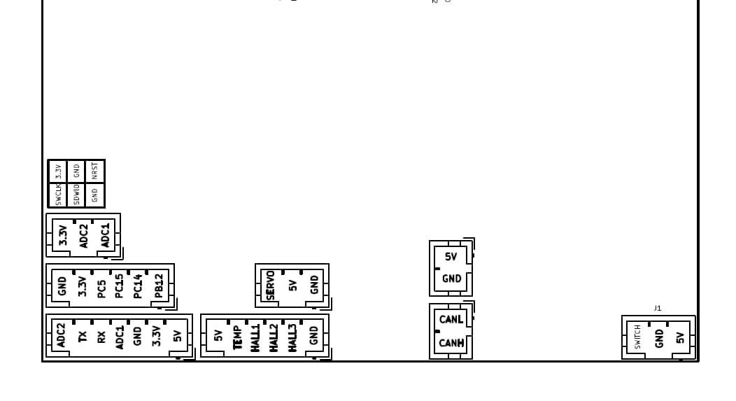
First thing to do is to ensure your pin-outs of the receiver cable and your controller match, and re-pin the connector as needed. For UART, use your controller’s 7-pin UART port. For PPM, use your controller’s 3-pin PPM/Servo port. For reference, I will include this process in relation to the BKB Voyager and the Little FOCer v3/3.1.
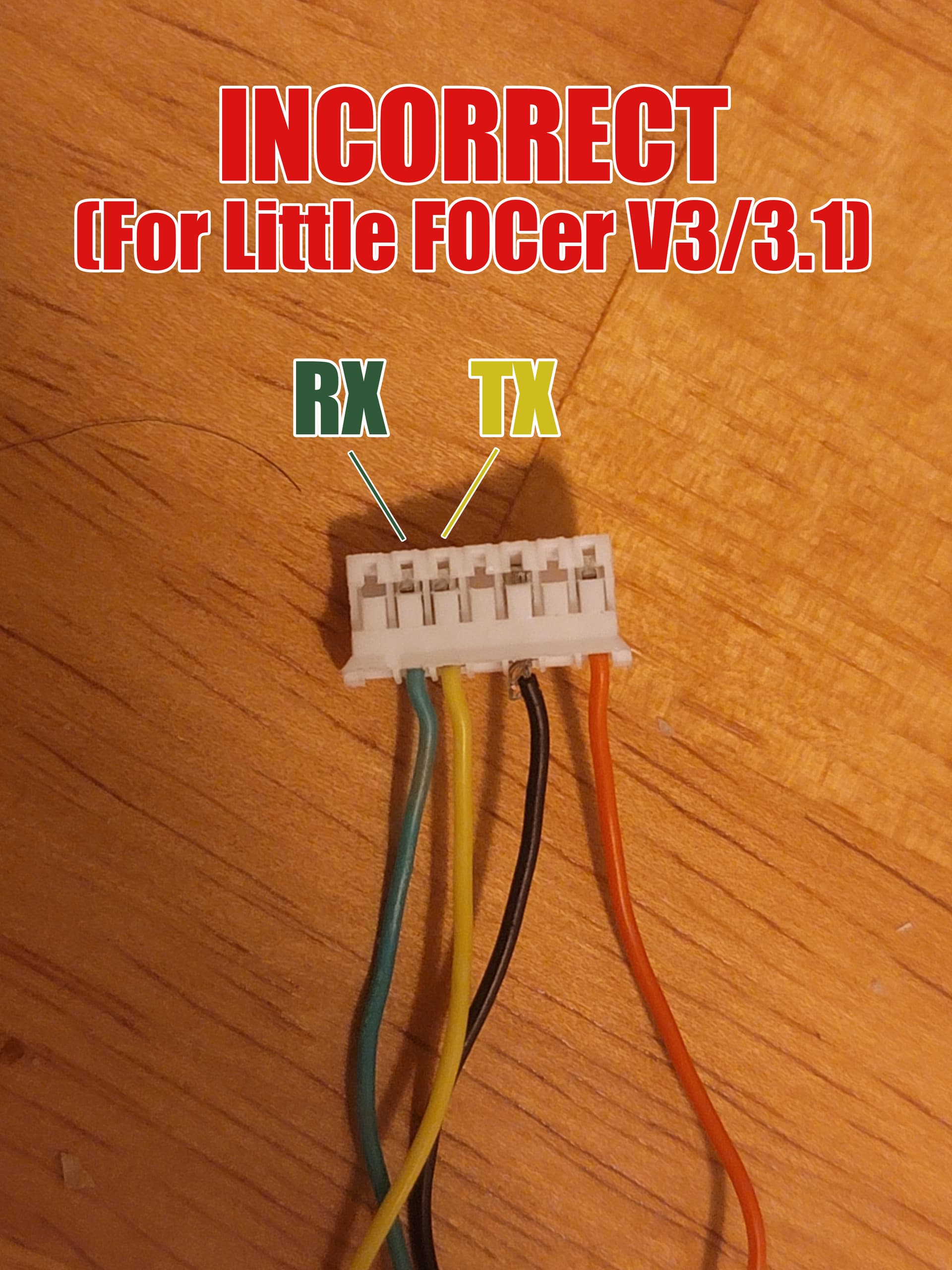
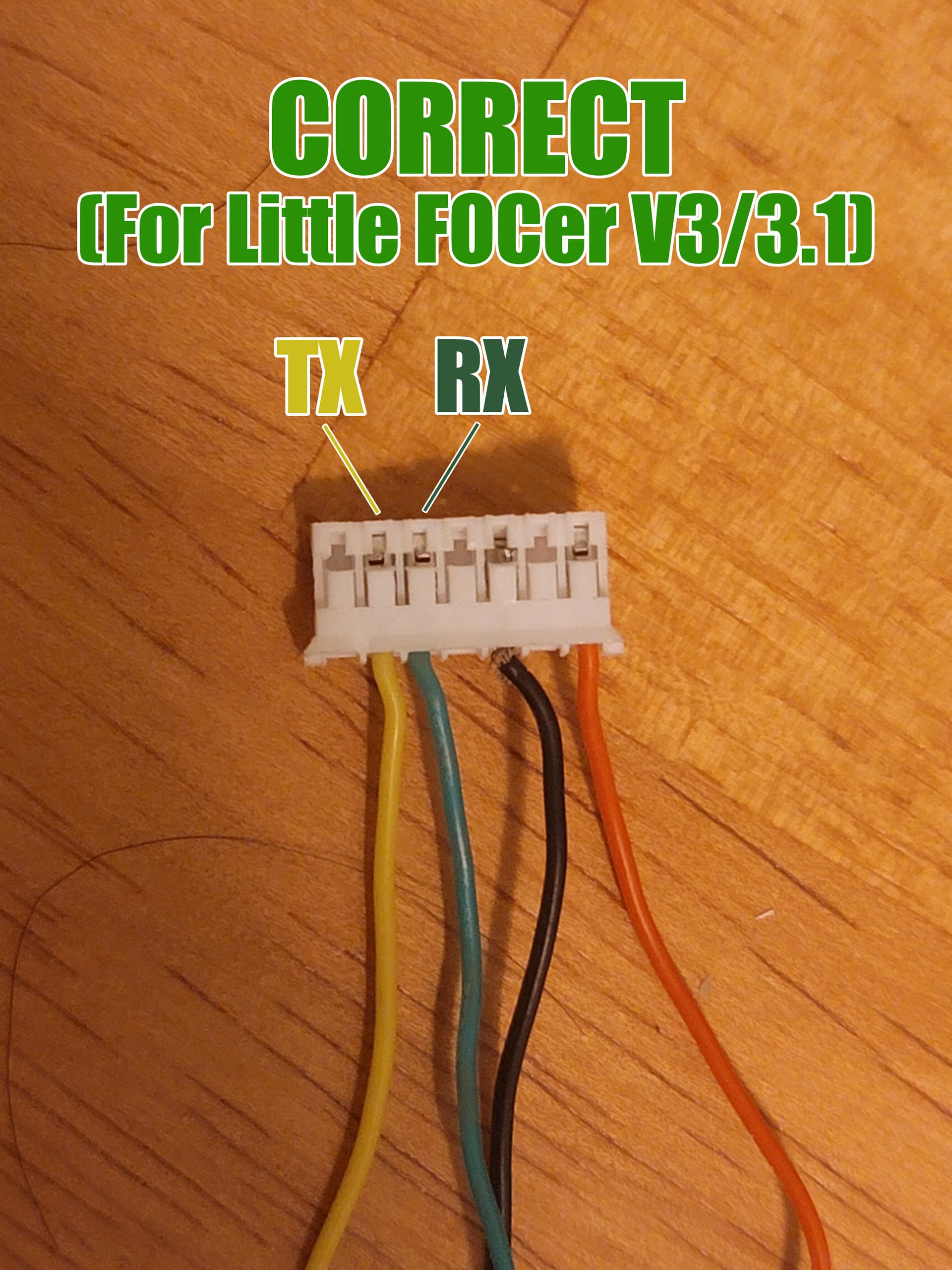
When referencing the Little FOCer v3/3.1’s I/O (UART port in bottom left) and comparing against the receiver and 7-Pin cable for the BKB Voyager, we find that the RX and TX wires need to be swapped to match the pins on the controller.
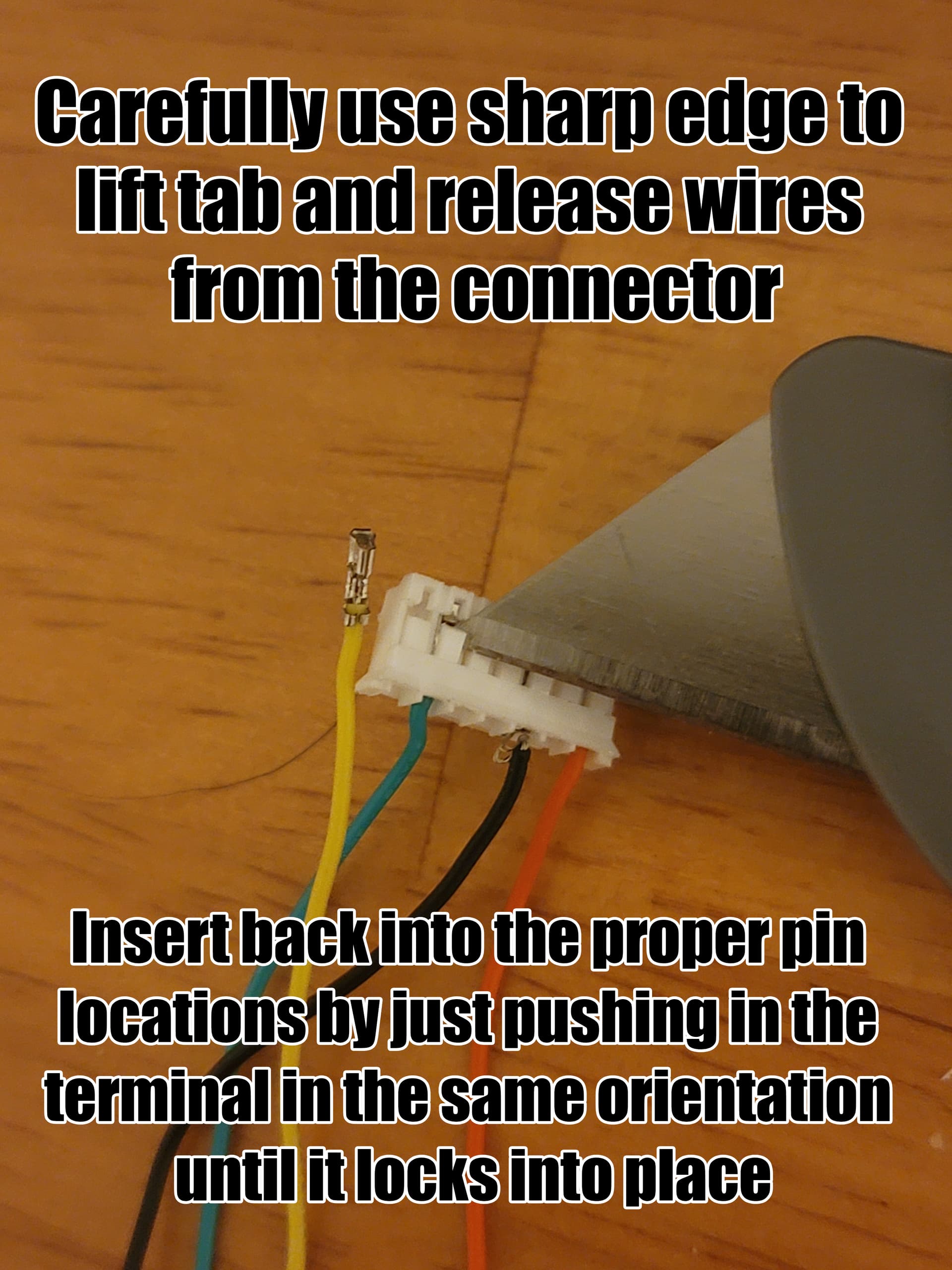
To swap these wires, you can use a sharp edge to carefully lift up the release on the JST connector and free the wires, then carefully insert them back into the proper pin locations in the same orientation until they lock into place. This video guide walks through this simple process.
Remote Syncing and Setup:
Once the connector is prepared, plug in your receiver and follow the manufacturer’s guide for syncing and setting up the remote. For example, here is the guide for the BKB Voyager. Ignore any steps for configuring the VESC app configs, as we are not using the remote for the traditional use case of driving the motor. Ensure that it is connected properly. For UART, you can check this on PC by going to the VESC Remote tab under App Settings, and enabling RT App from the right sidebar. There should be a readout for your throttle position at the bottom of the menu.
For PPM remotes (NOT UART), the throttle values must be calibrated through VESC Tool. This can be done through mobile VESC Tool by going to App CFG, tapping the “…” button in the bottom right, and going through PPM Mapping. This also confirms that you have a working connection to your remote.
If everything is looking good, be sure to secure the receiver to your enclosure in some way to prevent any rattling, movement, or potential damage during riding. Once this is done, feel free to close it back up and put your board back together.
Float Package Configuration:
Once your board is rebuilt and solid, all that’s left is to enable Input Tiltback in the Float Package. Navigate to the Float Settings tab, go to the Remote menu, and set your Remote Type to either UART or PPM depending on your remote.
The Max Tilt Angle will scale what throttle positions equate to what tilt angle, with 100% throttle back or forward being max angle of nose up or down tilt respectively. The Tilt Speed determines how quick the setpoint adjusts to the angle that matches your throttle position, with faster tilt speeds feeling more responsive but can be more twitchy and dangerous if not used carefully. The Deadzone determines how far the throttle must be pushed away from center before it starts responding. This can be useful if you find that at a centered throttle position, your Input Tiltback Setpoint (can find in AppUI Tab) isn’t resetting to 0°.
And with that, that should cover most of everything! If you run into any issues or have any questions, please feel free to leave them here. As I mentioned, please be diligent in making sure the pin-outs match between your receiver, cable, and controller. Enjoy your board’s new capabilities!
Common Problems
-
Board makes weird noises as soon as the remote is engaged
** you may have followed the BKB remote setup guide telling you to set “AppCfg” - “VESC Remote” - control type to something other than “Off” -
Remote doesn’t work at all, zero reaction from the board despite all configs looking good.
** check that your RX/TX match the correct picture above, most BKB Voyagers require those wires to be swapped