To make a long story short. I have an Error 16 that created the first task for buying a new BMS. After that one too fried, the decision to go to a Vesc-operated build became the deepest concern, which has been so epic to ride.
The second-bought BMS was not sending any cell data, so the wiring was correct. I checked this using the original FM BMS and got some data, but it had the same lousy cell data that caused me to purchase the second BMS.
Have a good read from the esp to the owie onto phone or web browser. Luckily I have an old XR lying around going to use that one till a good BMS is available that is easy to use and reliable.
So I went ahead and tried adding the diode. I was not able to get it to work but I learned a lot. I am going to move on to a smarter BMS so I have better control and more functionality. But I will unload what I learned in case someone wants to take it further.
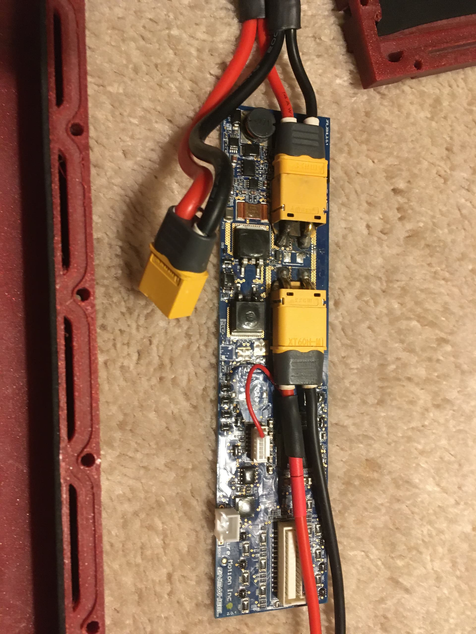
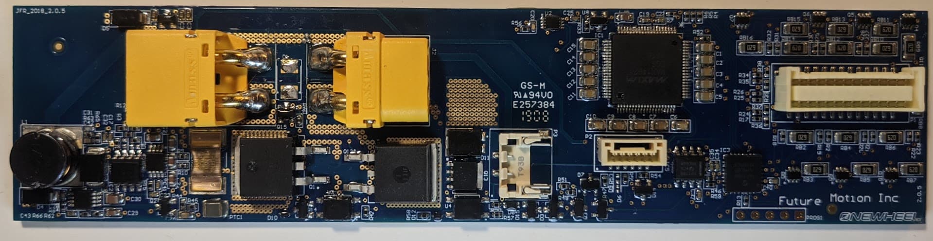
I believe there are differences between generations of FM BMS. Earlier BMS like the 4206, and maybe the 4208, and 4209 +XR have more integration with the controller than the later 4210, 4211, 4212 +XR and pint BMS. This is because they moved the charge port from the controller to BMS for the pint model. To reduce the number of inventory parts FM probably chose to make the same change to the XR BMS that they executed for the pint.
You will notice that there are some missing elements on the 4206 around the center of the board where the pint charger would connect to the board.
Without these elements to reduce the charge voltage, the voltage delivered to the BMS is higher than the BMS expects. This makes it overshoot. Once a cell hits 4.2V the BMS will shut off current flow between the XT connectors. What is supposed to happen is as it approaches the charge voltage, the current is reduced from 3.1A to .2A, but since the charge voltage is too high, current never reduces. This reduction in current is what allows the BMS to balance so it will not balance.
I was on the right track but I don’t think my part selection was exactly right. What you need is a simple circuit that reduces the charge voltage from 63.3 to about 62.0 at 3.1A. From there, as the battery approaches the charge voltage the circuit should reduce the voltage from 63.3 to about 62.7-62.9 at .2A. This will allow for a slower approach to max voltage and enable balancing.
Oh shit I’m on a 4206. I’ve got a charge/discharge setup right now that’s been causing me a few small issues, but I’m about to switch over to charge only. Did you ever discover anything else about this?
If you want to added a diode to reduce the incoming voltage slightly then you can do that as some have reported issues, but I haven’t seen this problem. Could also be related to some chargers being calibrated slightly differently I suppose.
Are your cells balancing that way? It sounds like the way I need to wire everything up, but if I’m in there I want to only have to open the battery box a single time if I have to.
Did you use the diode to lower the incoming power or did you wire things up without it?
I’ve done it with and without the diode and it works both ways for the ones I’ve done. I just always make sure to put a 10a fuse on the positive coming from pin 3 of the XLR.
I did not do any more work on this after trying my 4206 and 4209 with the same issue. I charges but not to 100% because of the high voltage cut off. I just rock an external, charge only LLT BMS now.
I think I might see the same behaviour you’re talking about where the charger cuts between green/red/off, but mine all eventually charge all cells all the way to full and balanced between 4.20-4.23v
I think it still is applying full 3amps possibly, but hard to tell as it is flashing. I may consider adding diodes going forward, but I have not experienced any issues other than the odd blinking of the charger and possibly supplying more than desired current near the top end.
Another solution could be to tune the charger, but I’m not sure if that is easy to do on a FM charger… I might look into that instead of adding diodes.
That makes sense. Now that you mention it, it is really a charger issue not a BMS issue because the BMS is doing what it is supposed to. The FM charger output is just a bit higher than we need for these older models.
I have switched over to using the following combo for charging. I have been using the DC-DC module for years for mobile charging. It is very reliable and simple to use. You can just set whatever voltage and amperage you want. It will automatically lower the amps as it approaches the voltage. Power supply, DC-DC
What pin should be used to jump the purple wire on the 16pin connector? Also pins for the charge wire (blue, black, white, green)? Or does this setup need custom harness with cable gland?
You talking about the wire that goes from the 3rd xlr to the 16 pin? I believe it’s the farthest to the left on top. Probably should double check, I know for the momentary setup that’s the one I got hooked up, that tk talked about using so that the momentary setup isn’t (highly recommended) tbh that’s is a great setup other than you gotta take the max to 25/26 &-30 in order to get the thing not to shit off when sitting in curbs. But once that was figured out it rode like a dream. We’re going ti hope it hooks up tonight and powers on otherwise … I can’t keep riding this damn fm xr controller it’s so dirty and feels like a barbarian board that Neanderthal used to run from dinosaurs during the ice age.
FYI on the OWIE github page there is a link that starts a tool to flash the esp board with the click of a button. makes it super simple, no need for the long tutorial.