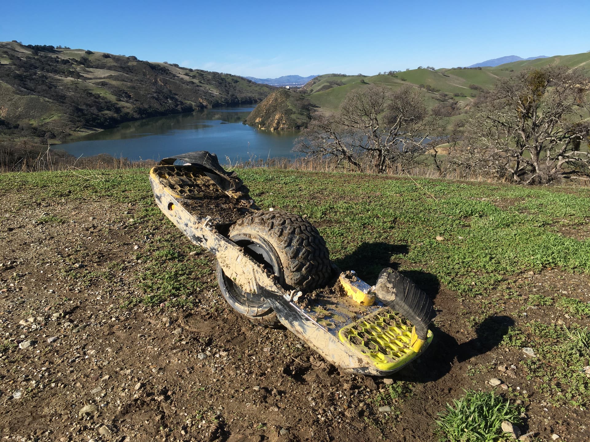
Starting a thread for my build. I have unique ideas about how I want my board to assemble and function. With this build I am looking to take advantage of my footpad design to allow for better cooling of the controller and better access to battery connections. Here are my files that I will be sharing in the interest of open sourcing. Here is my board before and after conversion.
Before:
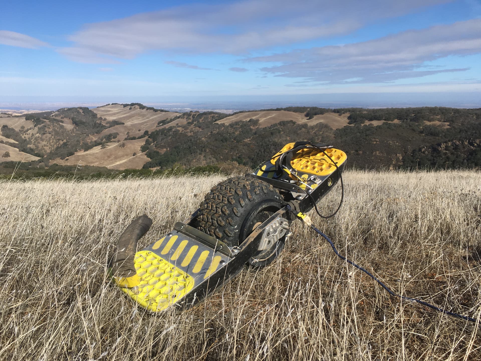
After:
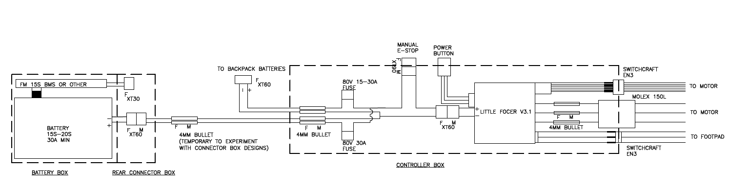
You’ll see I have quite a few custom mods. I will be focusing on the VESC specific mods but I’m happy to fill in any details. First, here is a diagram of my build.
We have 80V discharge fuses and holders. I respect the arguments against discharge fuses but since it is part of the VESC guide and I have a hot VnR cable, I think they are necessary.
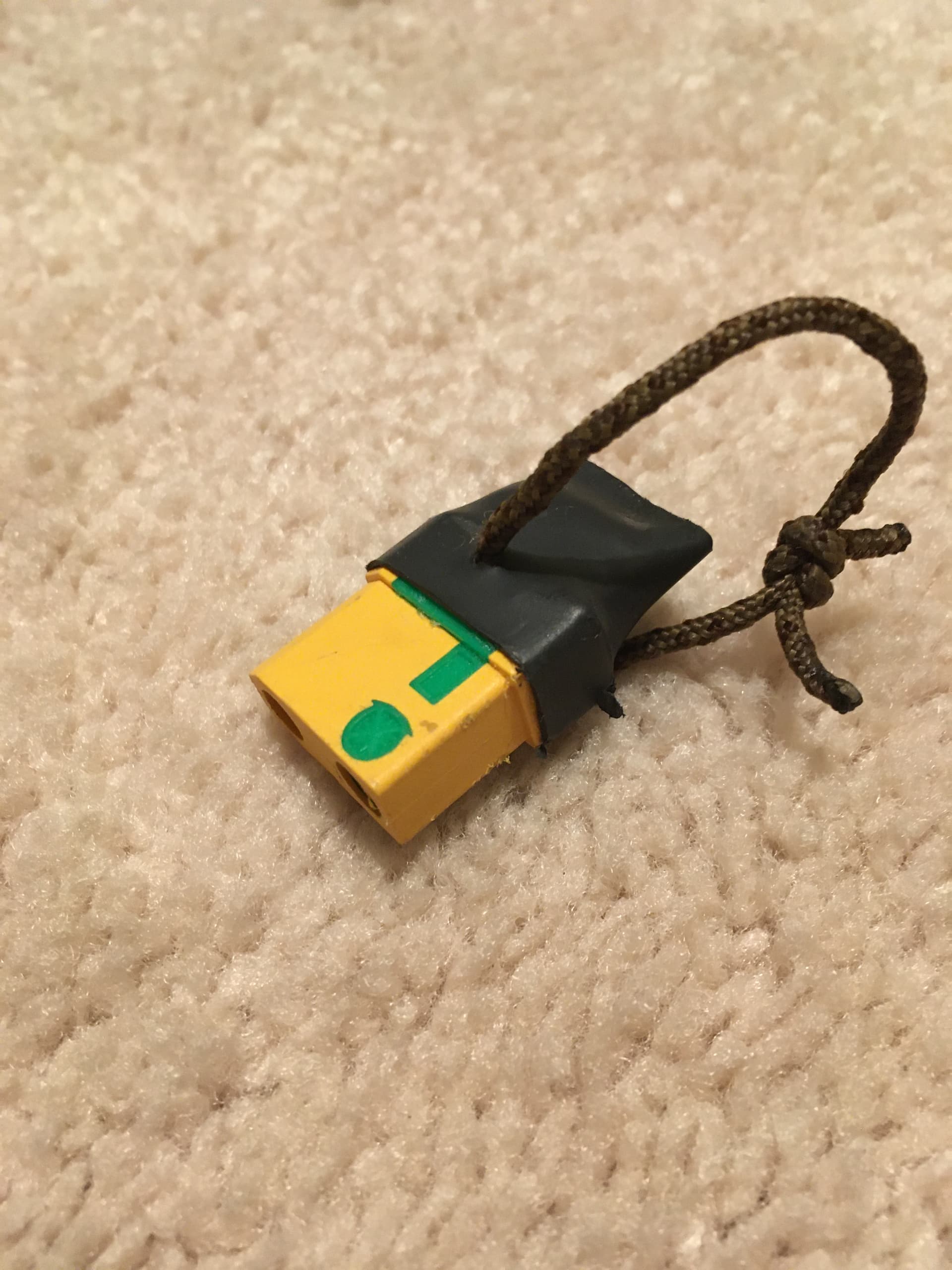
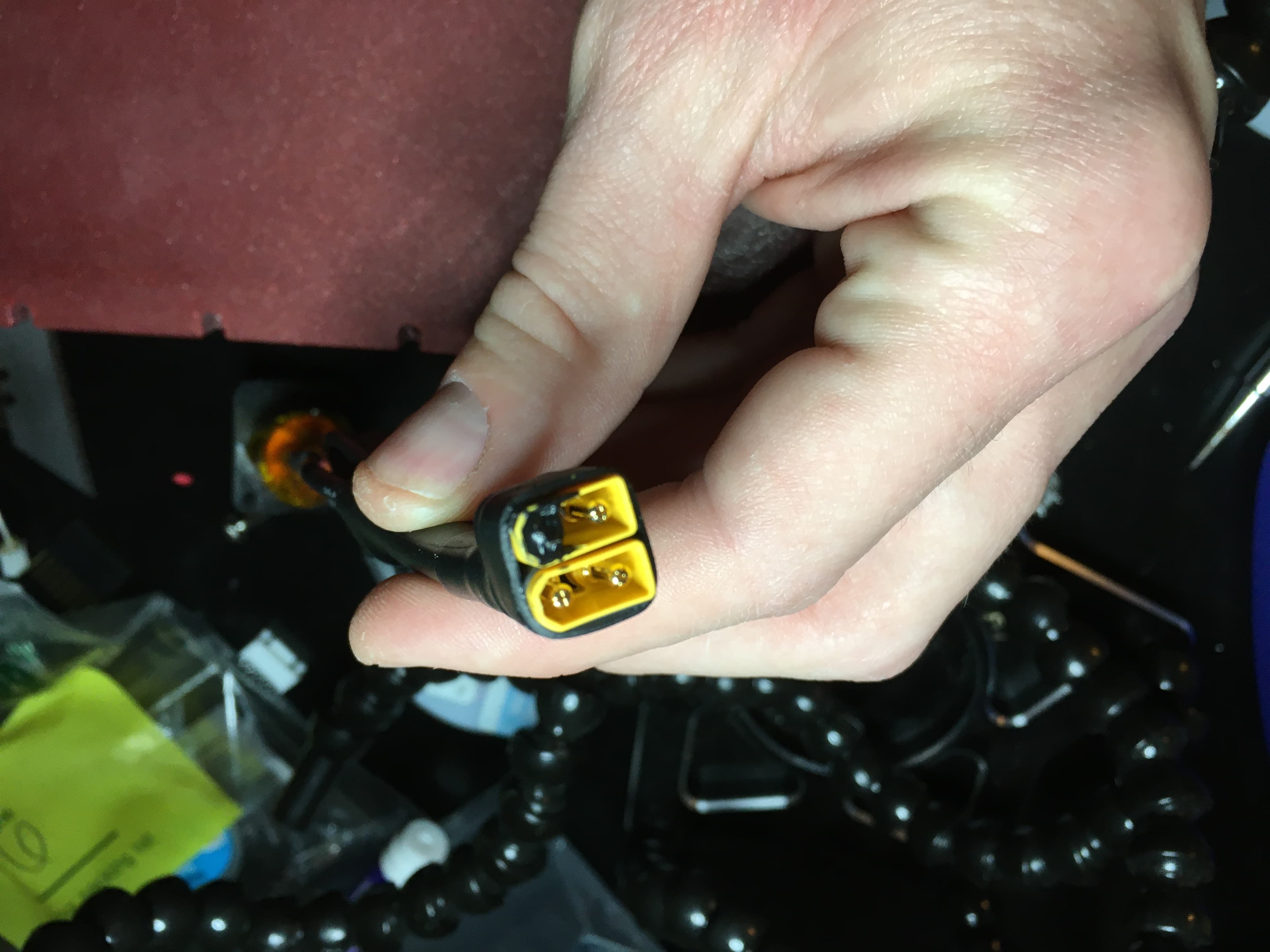
I have added a loop switch where the charge port used to be by using a XT-90E-M and XT-90S-F. Here is the loop key I made. It fits in the charge port hole pretty nicely:
For my power button I opted for a smaller size for lower volume and weight. Here is the switch I chose. It has no LED but that doesn’t bother me. I just push the board a little to see if the braking current is on.
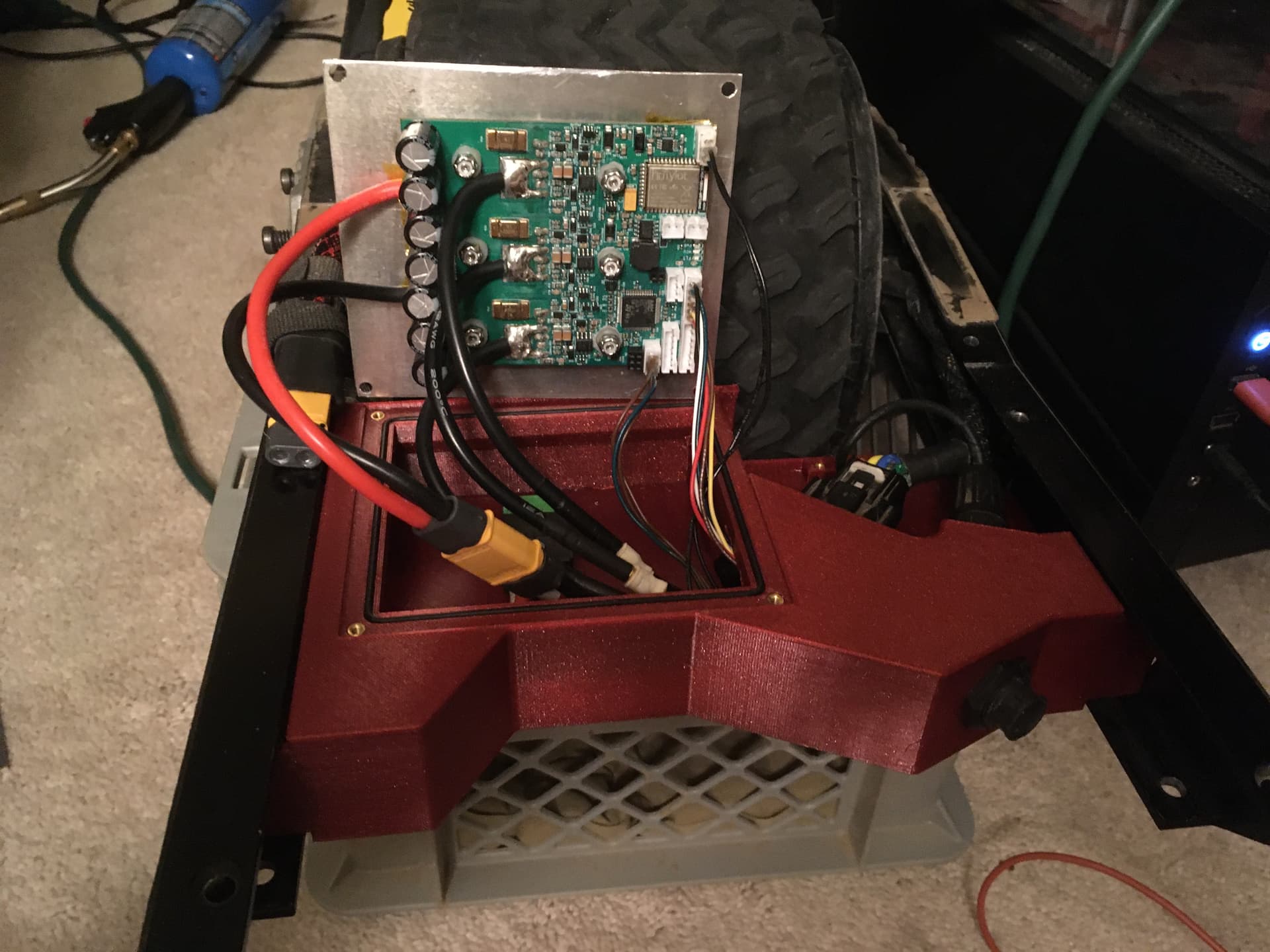
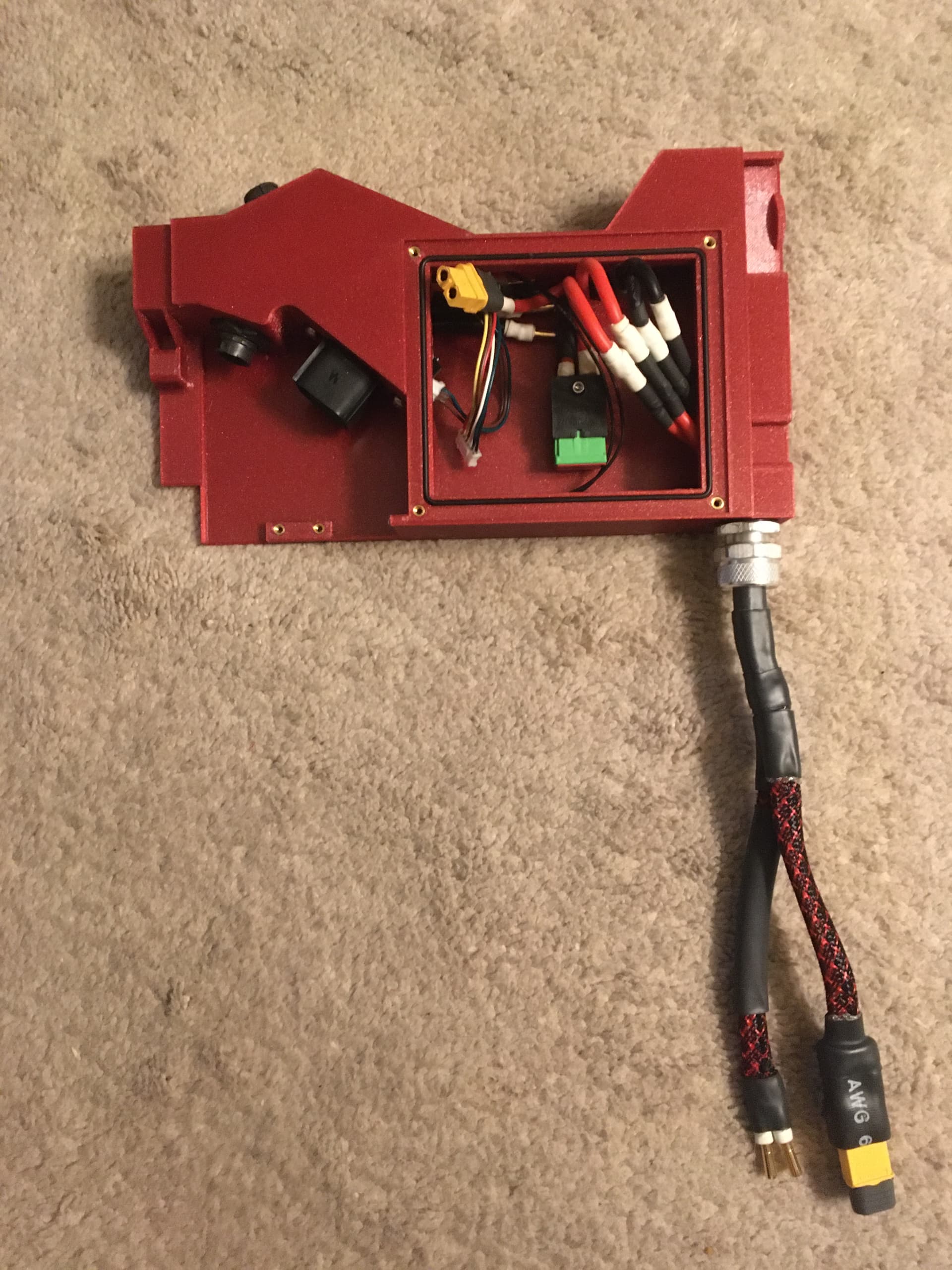
Here is what the control enclosure looks like before installation:
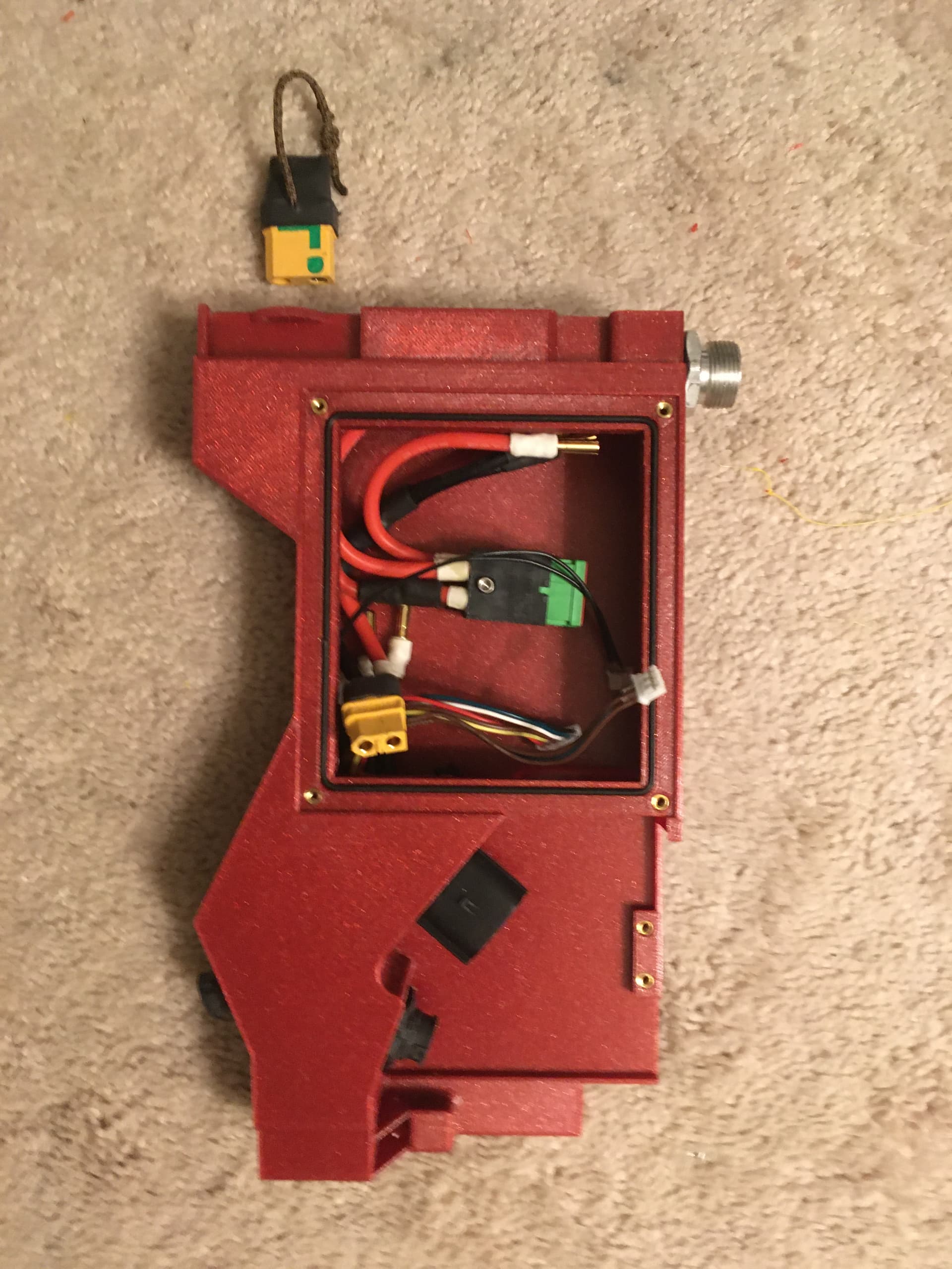
You can see the motor connectors on the bottom right and the footpad connector on the bottom left. Top right is where power comes in. I use this cord grip which is large enough to fit 4x 12ga wires and 4x female bullet connectors. This will not fit XT60 as I discovered.
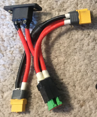
To install the XT90E-M I added two #4-40 brass heat inserts into it. Here is what that harness looks like. I changed the 2x male xt60 connectors in the upper right to bullets because I could not get the xt60’s through the small cord grip.
The XT90E-M is placed inside the box with a gasket. 2x 4-40 screws are applied from he outside to hold it in place. The fuse holders are held to the bottom of the box with a single 4-40 screw and heat insert shown in the previous picture of the box.
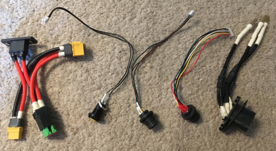
Here are the other wire harnesses I made and my power button. Pretty standard stuff.
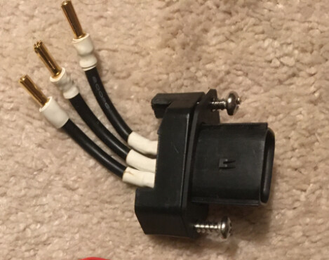
I later changes my motor adapter to this after seeing Mario’s build guide and changing my box design a bit.
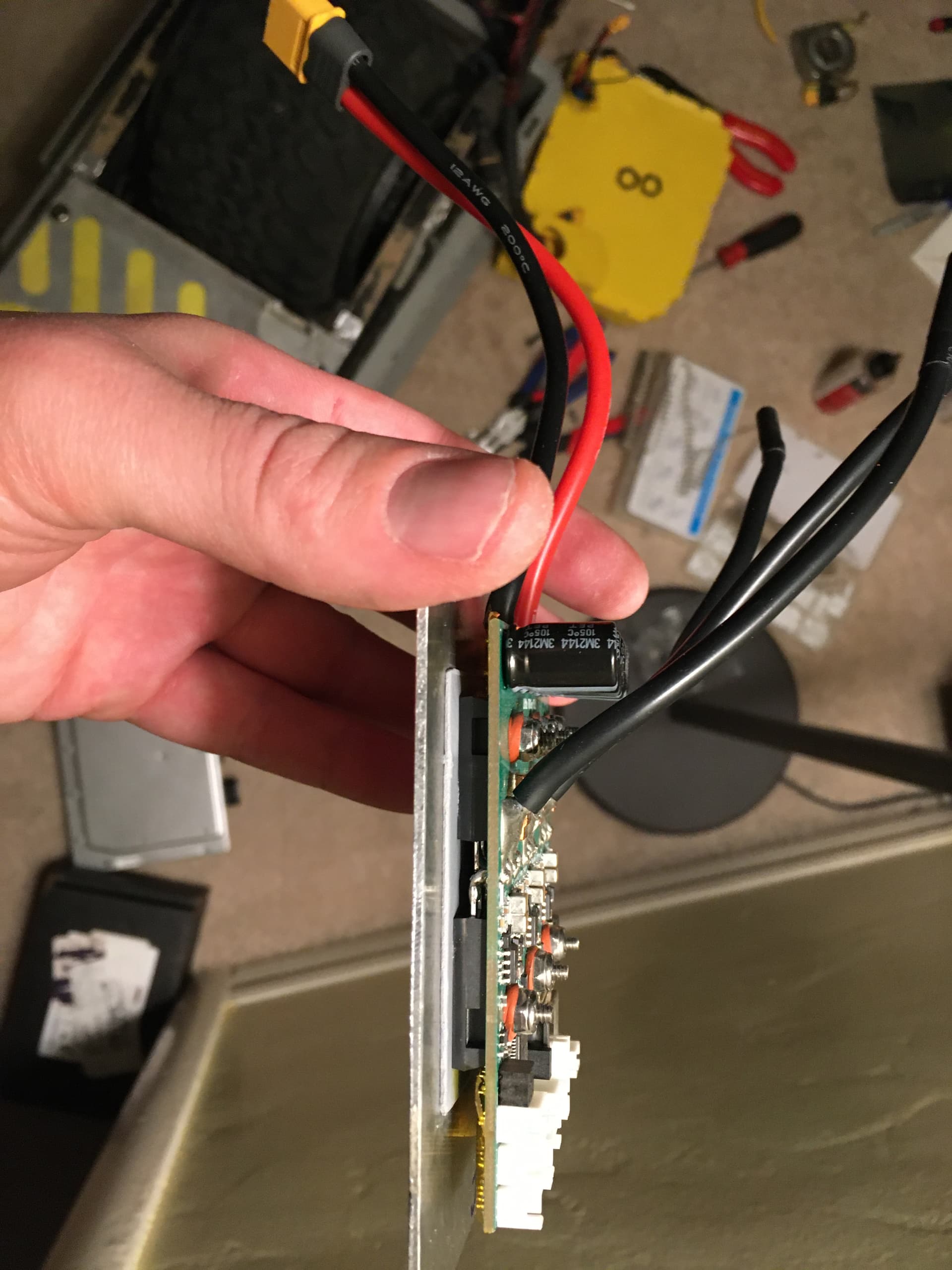
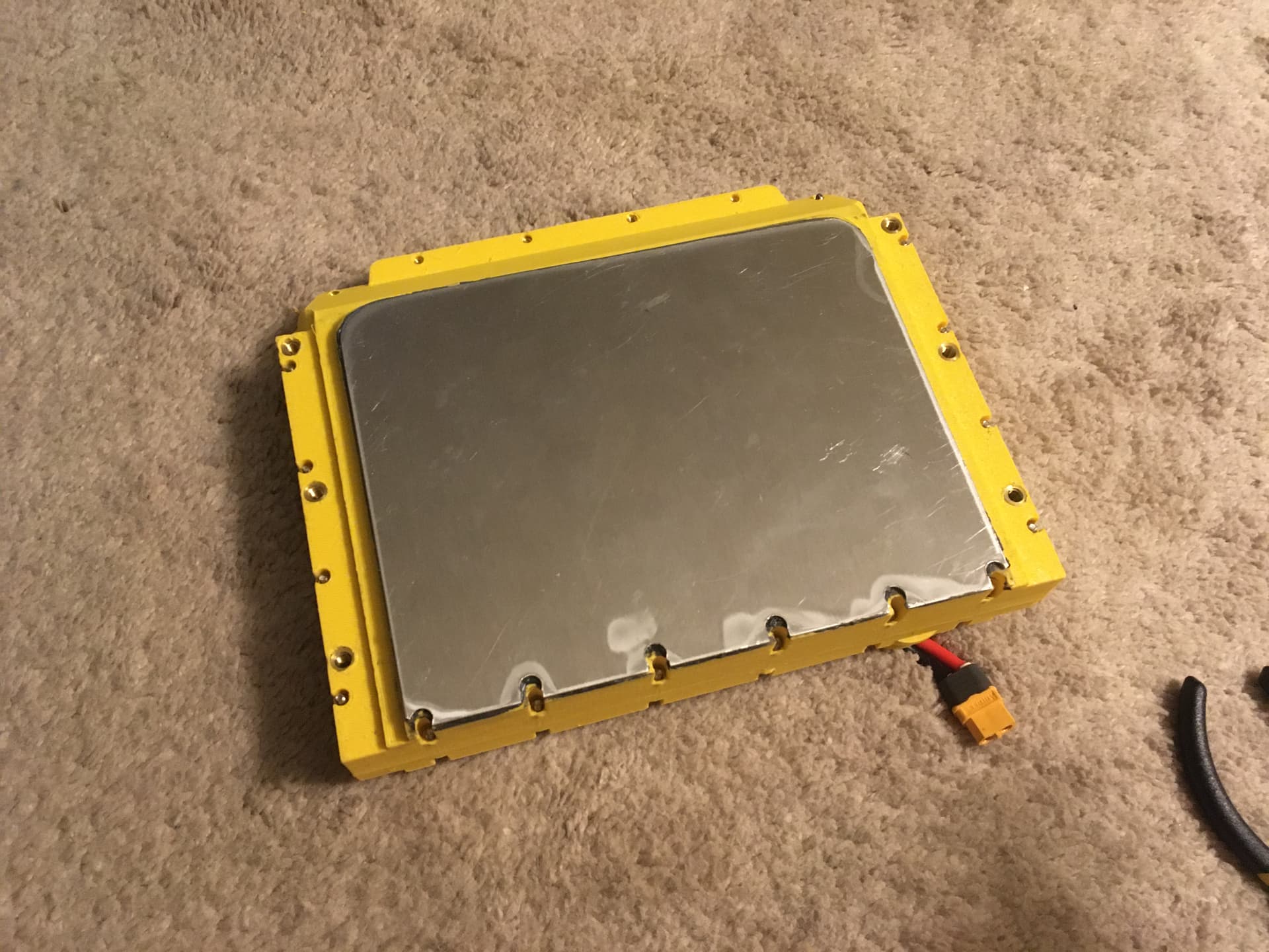
Here we are with the focer installed and ready to close the box. The heat sink is 1/16" aluminum. It will seal to the 0.07" diameter o-ring on the box. 4-40 screws and heat inserts hold it in place.
Here is a closer look at the focer on the heat sink I made. I used 4-40, 5/8" length press fit studs. I used “washers” made of Durometer 70A, 1/8" thick, silicone rubber. I figure this will hold the board whithout marring the surface. Silicone rubber is very heat tolerant and resistant to wear. M3 nylon washers should be fine though. 1mm heat pad.
Here is a better look at my power harness. We have 4x 12ga wires going into the cord grip. They are bound together with heat shrink. I use z-block heat tap to prevent water ingress. It’s kind of like hot glue in tape form. The wires that terminate with an XT-60-F are for my VnR cable to my backpack batteries. The 2x male bullets will go to the on-board battery. I only added these bullets because I was not sure if I was going to change the rear connector box design. This allows me to easily do that. In the meantime this connection is water proofed with z-block and heat shrink. I used this sleeving which is that same stuff that Sonny Wheels used to sell on their harnesses. I used 1/4" but you might consider 1/2" for 2x 12ga.
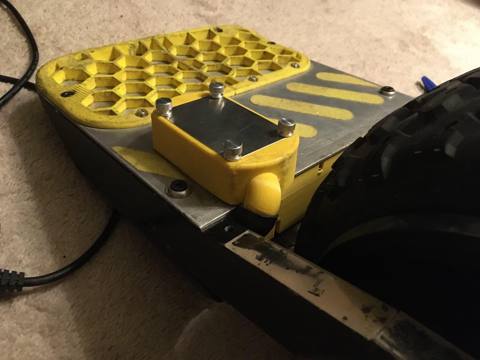
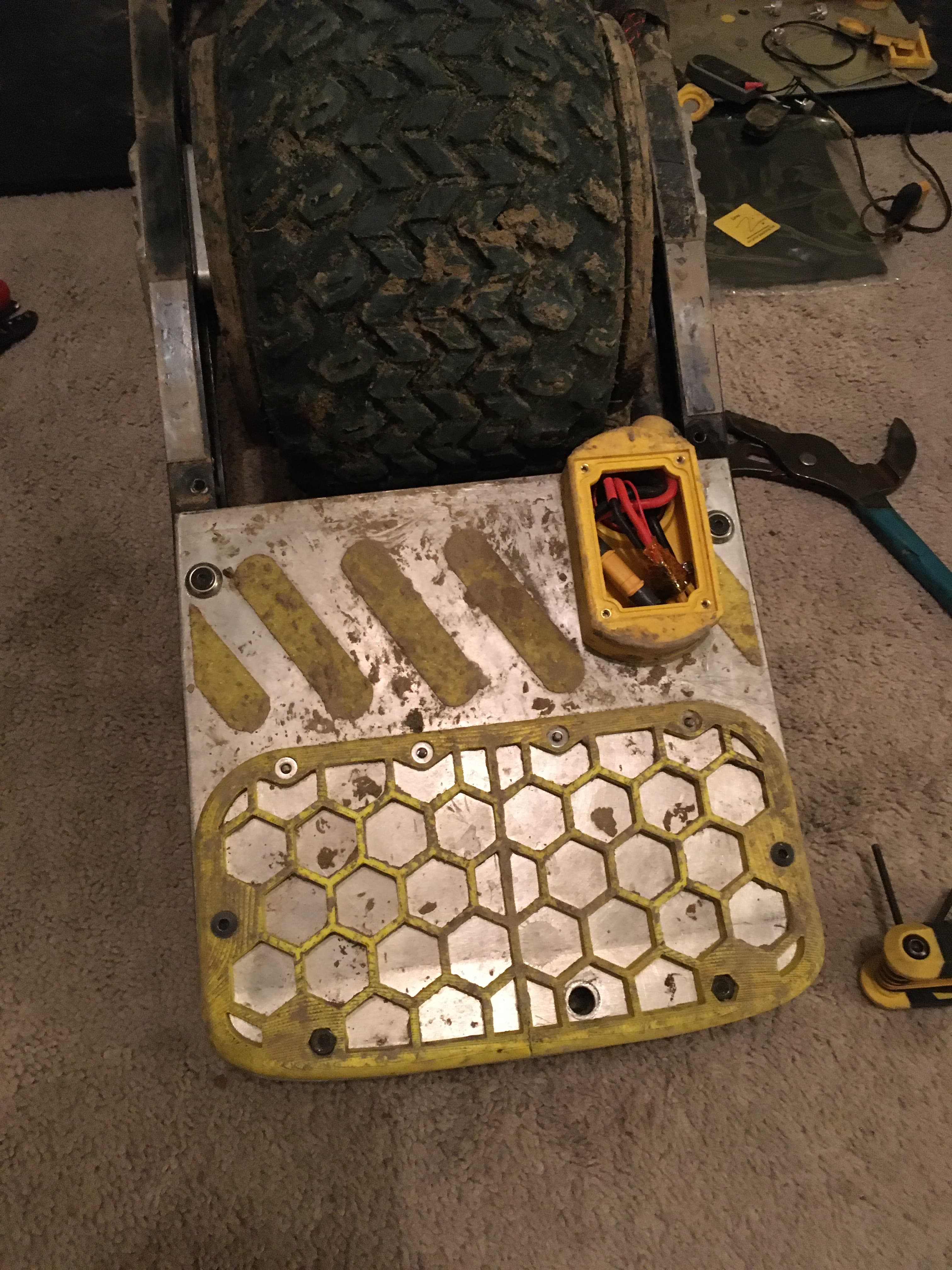
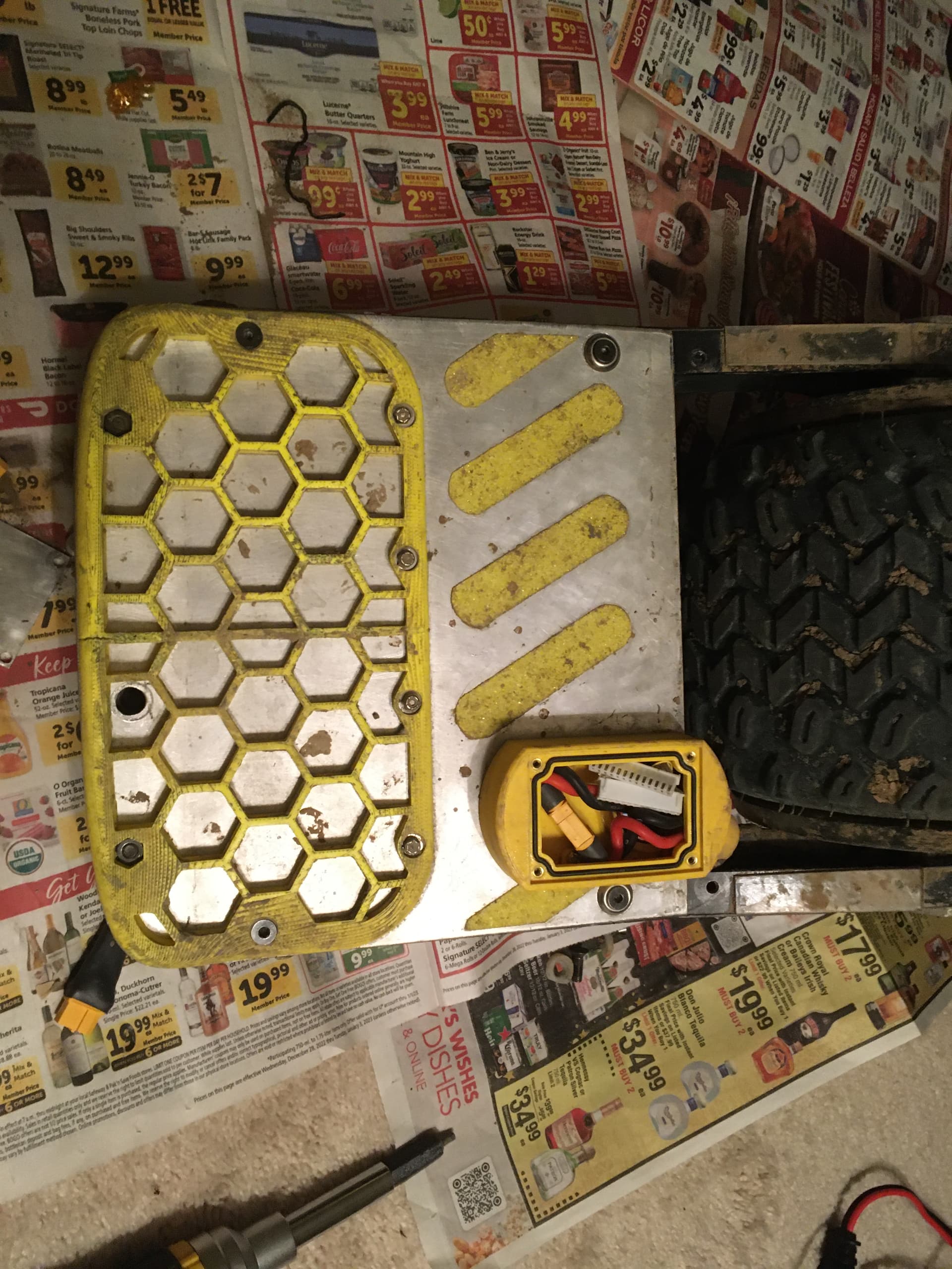
Here we have the controller box, motor and footpad all installed. You’ll see we have plenty of extra room for the handle. Makes it much easier to carry. I was able to move the connector for the footpad to the other side of the box because my footpad design uses two IP67 switches. I can drill a hole almost anywhere in the footpad to pass the wires through.
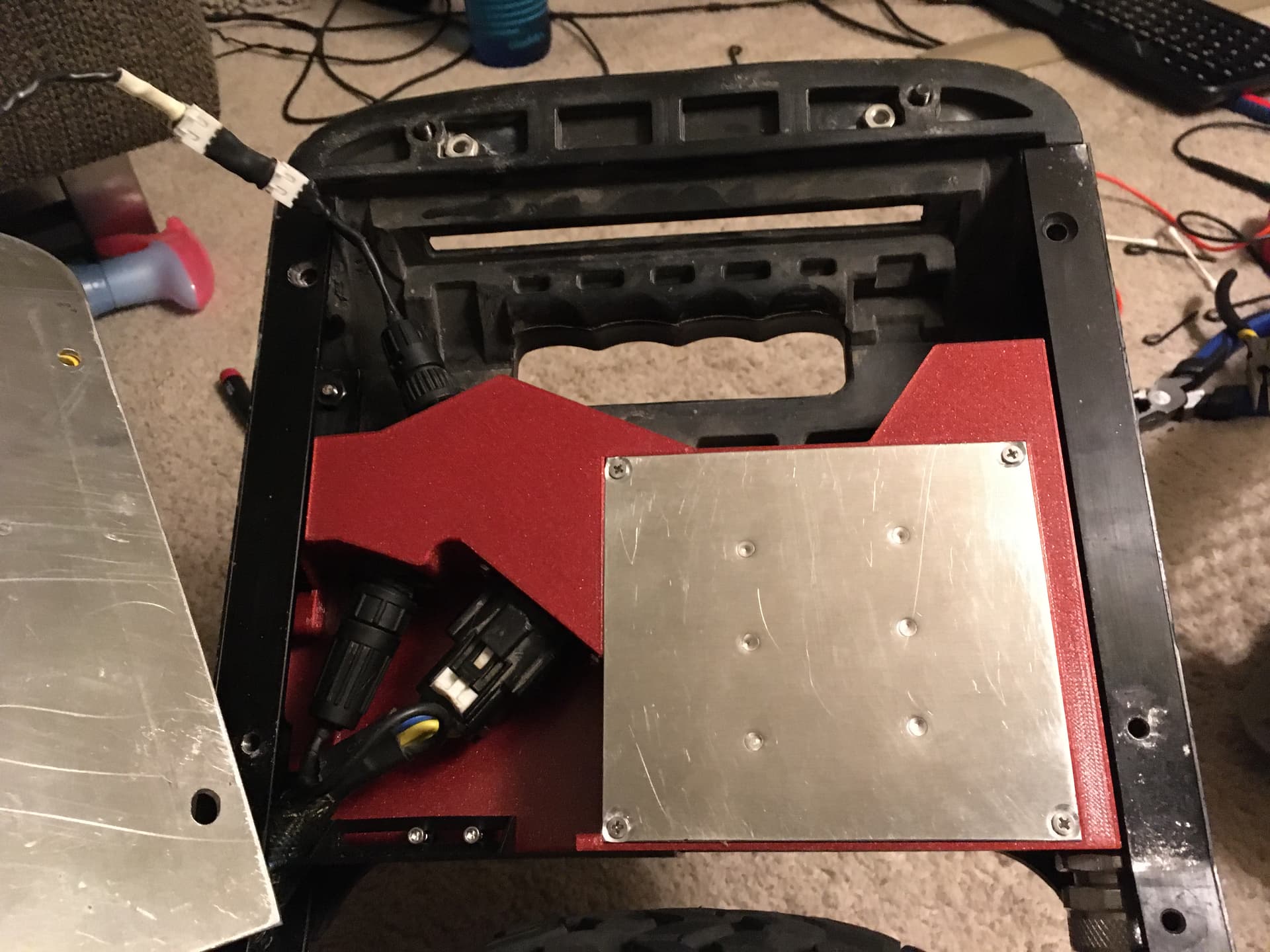
You’ll notice I flipped the molex connector for the motor over. This will allow for easier motor swaps. No need to take the bumper off. The position of the molex connector took a lot of trial and error because that harness is so stiff. Previously the molex was closer to the power button but I had to switch it with the hall sensor connector to make it fit. On the bottom left you’ll see a black piece of plastic held by two bolts. This is a sliding door to keep material out of the motor connector area.
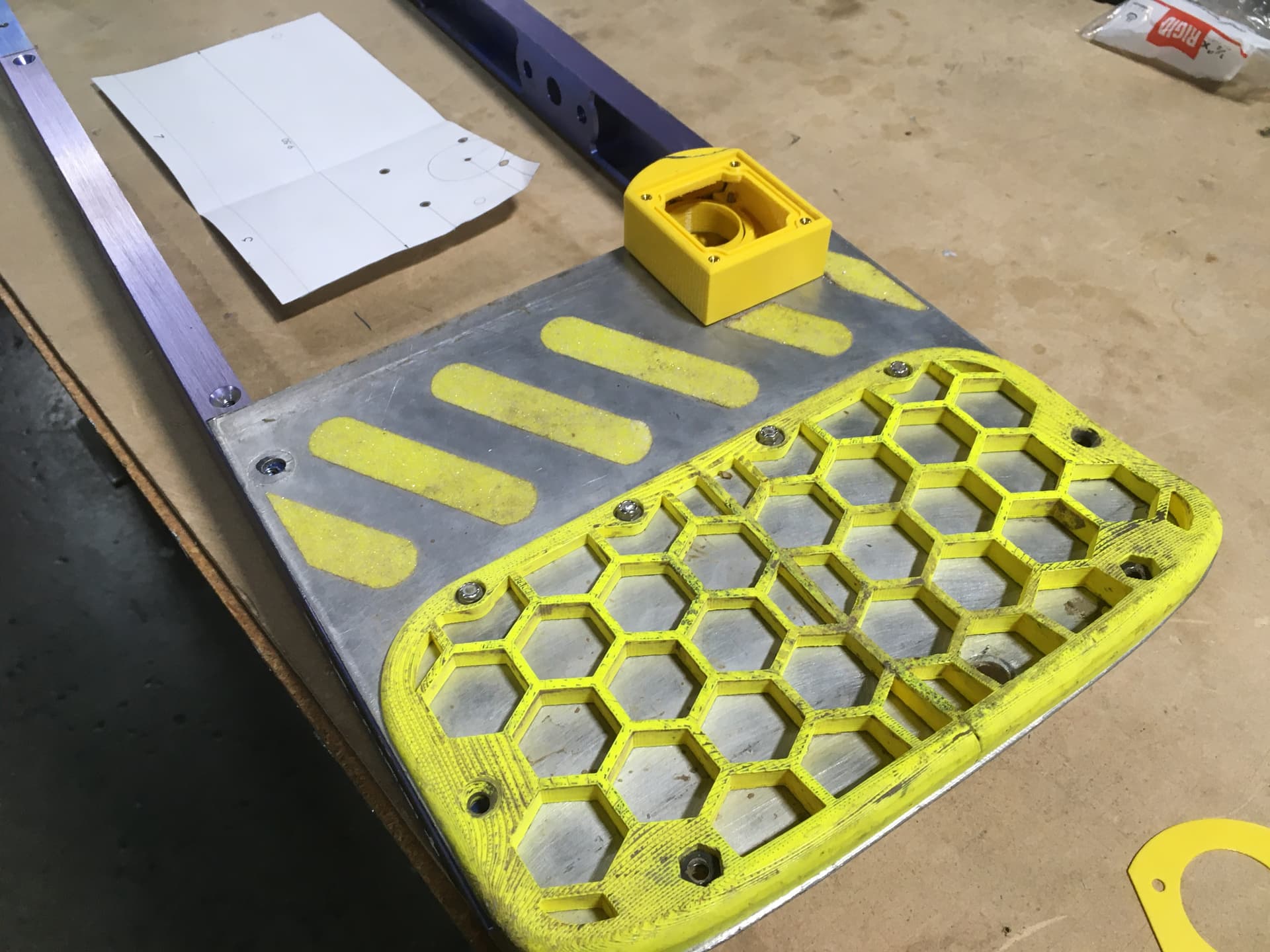
The main principle of this design is for the best performance of the focer without adding too much weight. My footpad is .09" thick aluminum and only weighs 3-4oz more than the stock pad. In order to leverage this as a heat sink, the focer heat sink is slightly above the height of the plastic enclosure. There is also some vertical tolerance between the box and the rails so that the box can be shimmed up slightly. This will put the focer heat sink in direct contact with the footpad. I have 0.5mm thermal heat pad that I could use between the two but haven’t yet. I am going to wait until summer to see which configuration is better: direct contact or thermal pad to make up the non-uniformity.
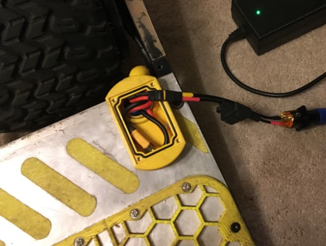
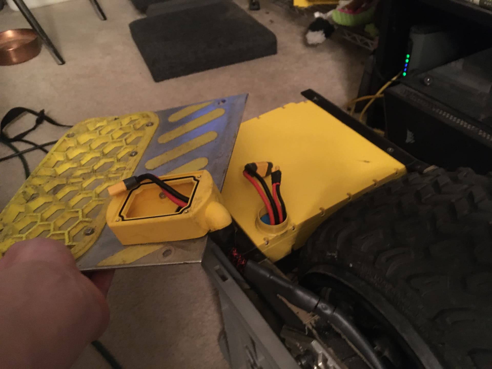
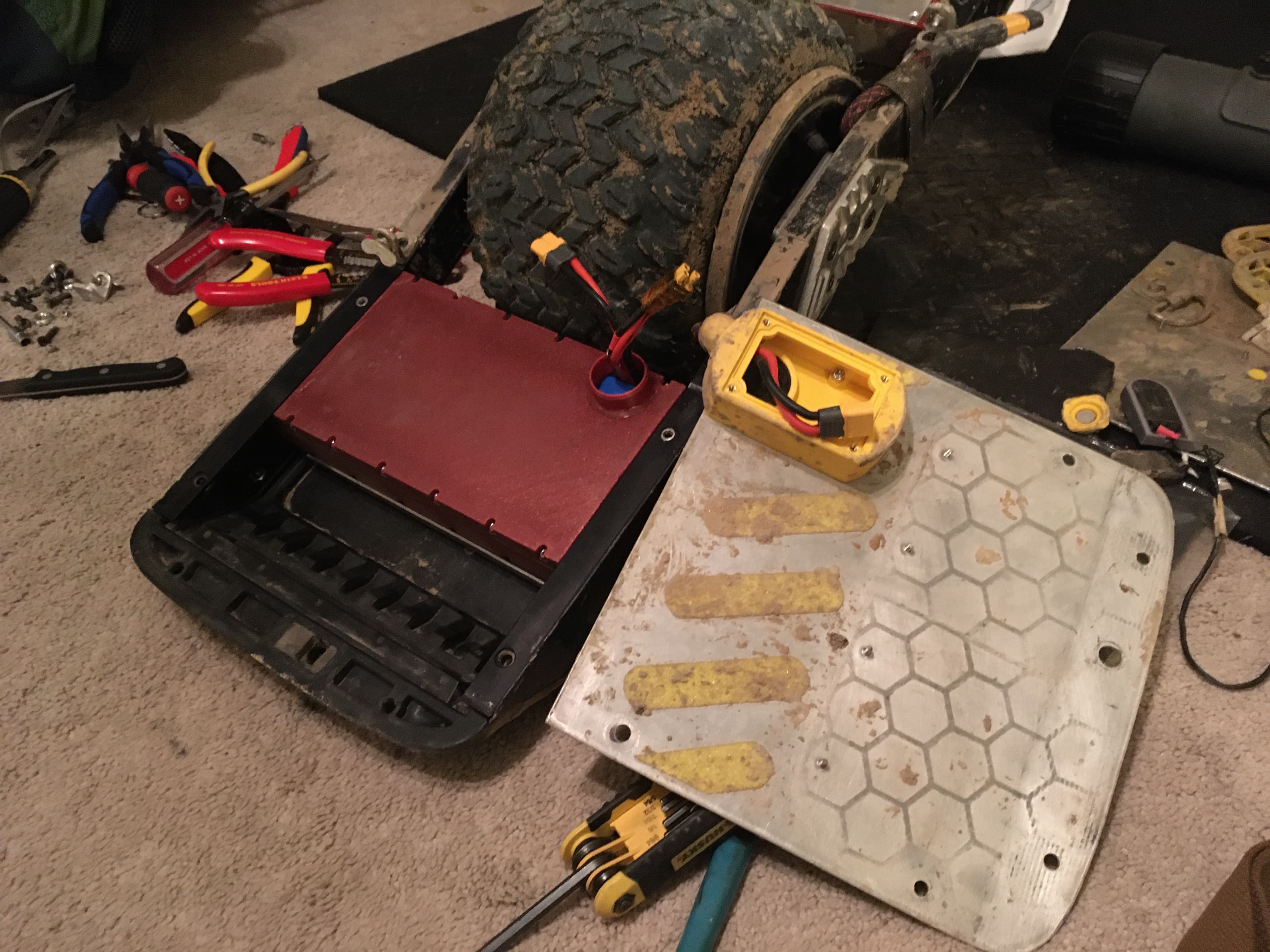
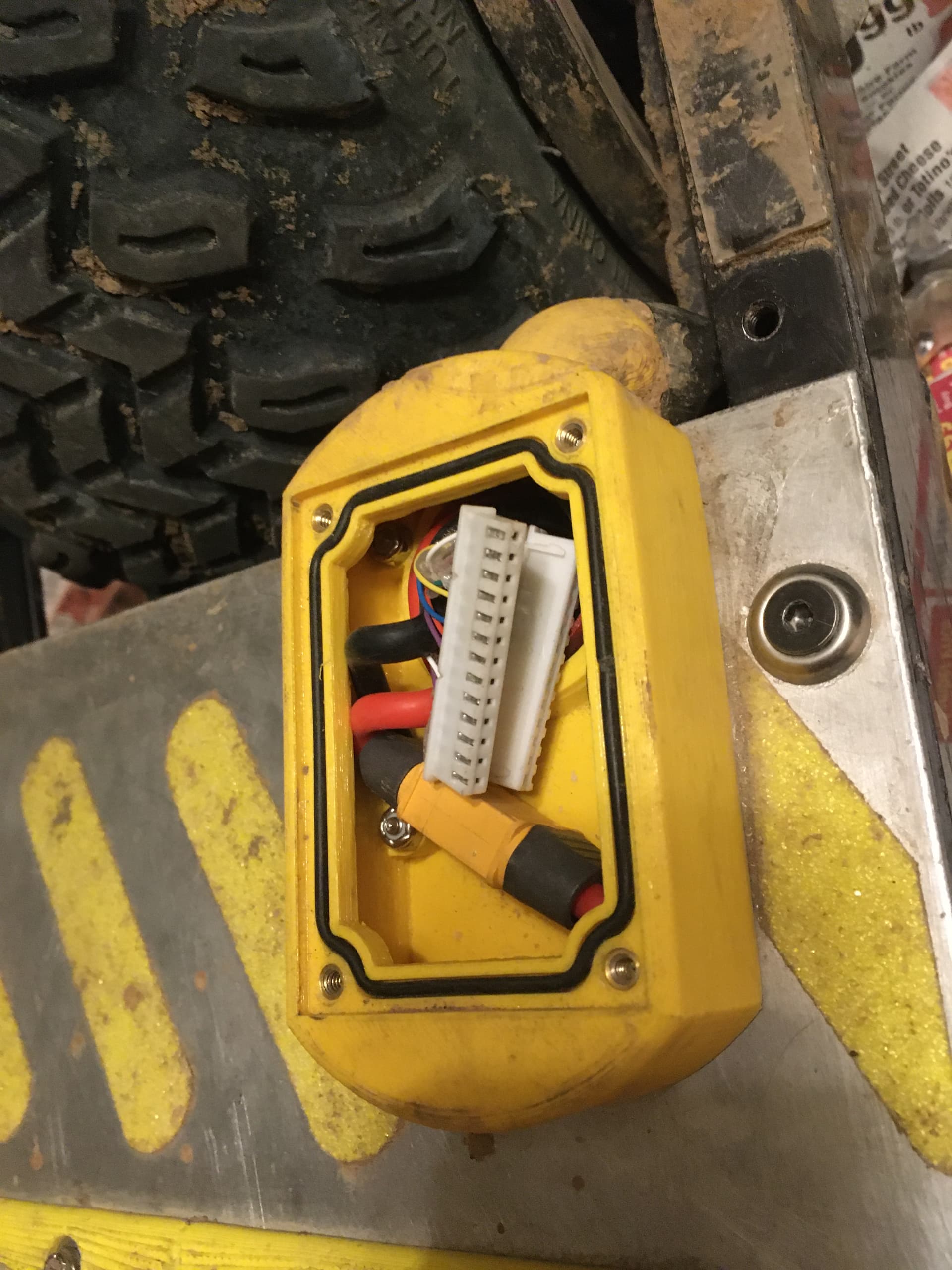
As we move to the rear footpad, the other main innovation is the rear connector box to access the battery connectors.
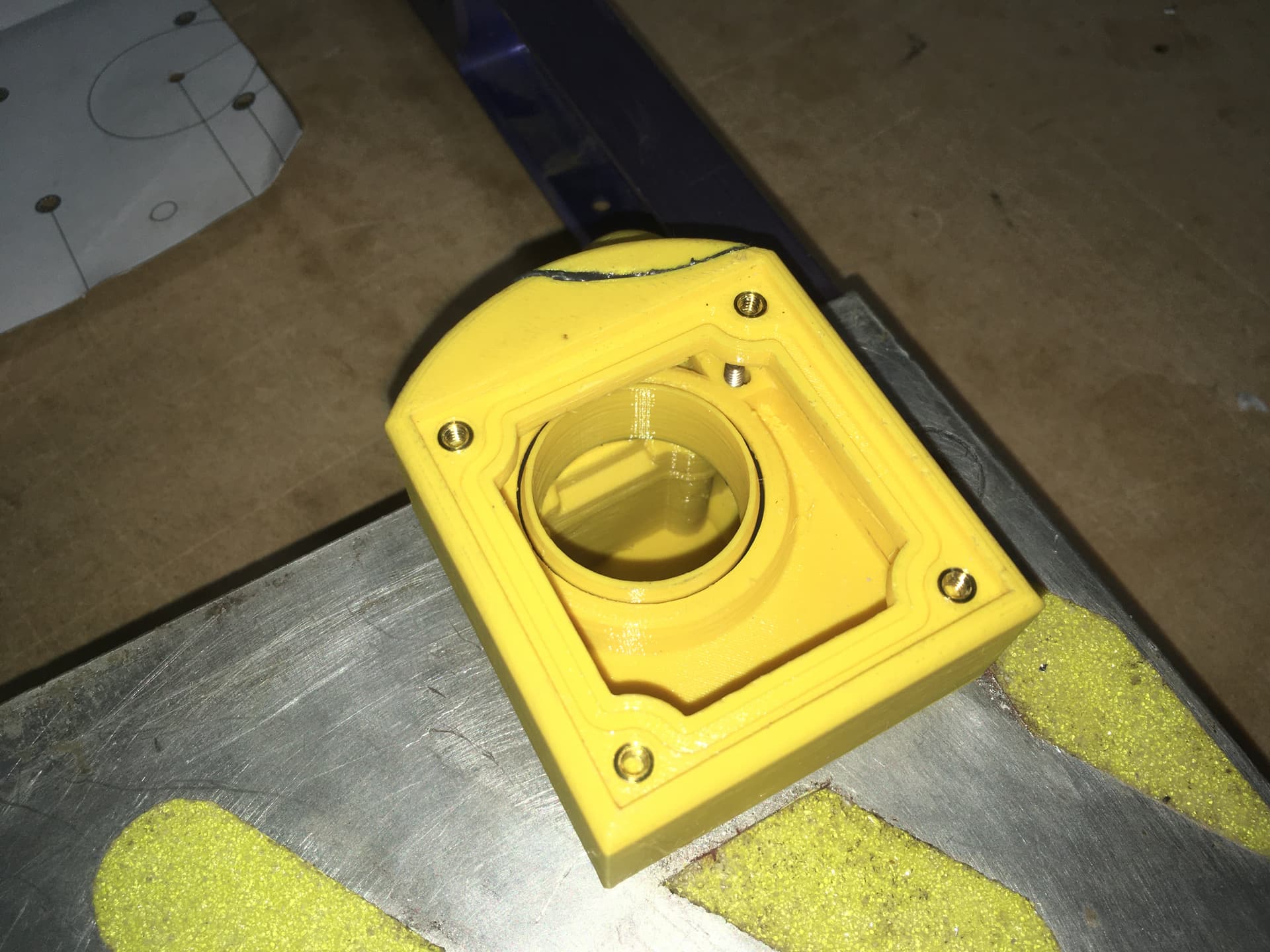
The idea here is that I want to swap battery without having to mess with the front footpad and bumper. This also allows for different BMS configurations. You could go with external BMS and have the balance connector in the connector box. You can do charge only and have a XT30 or similar which is how I am configured now. You can also put in a manual switch for a BMS.
The connector box seals with the port in the battery box via tangential o-ring. The box is fastened to the footpad plate via 4-40 press fit studs, 1/2" length. It has an o-ring groove for the lid to seal against and 4-40 thumb screws to hold it in place.
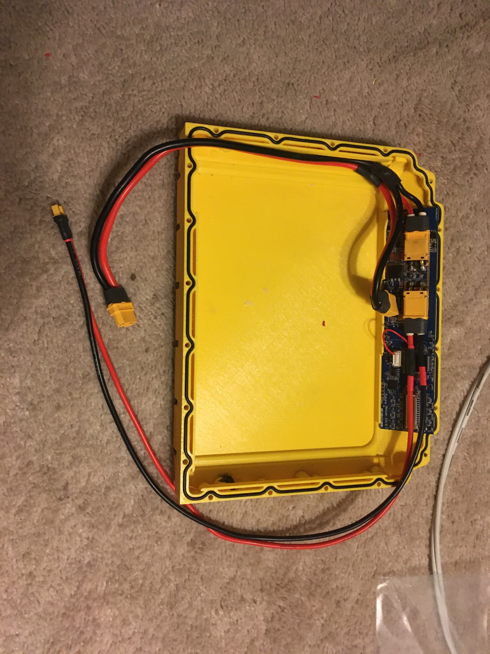
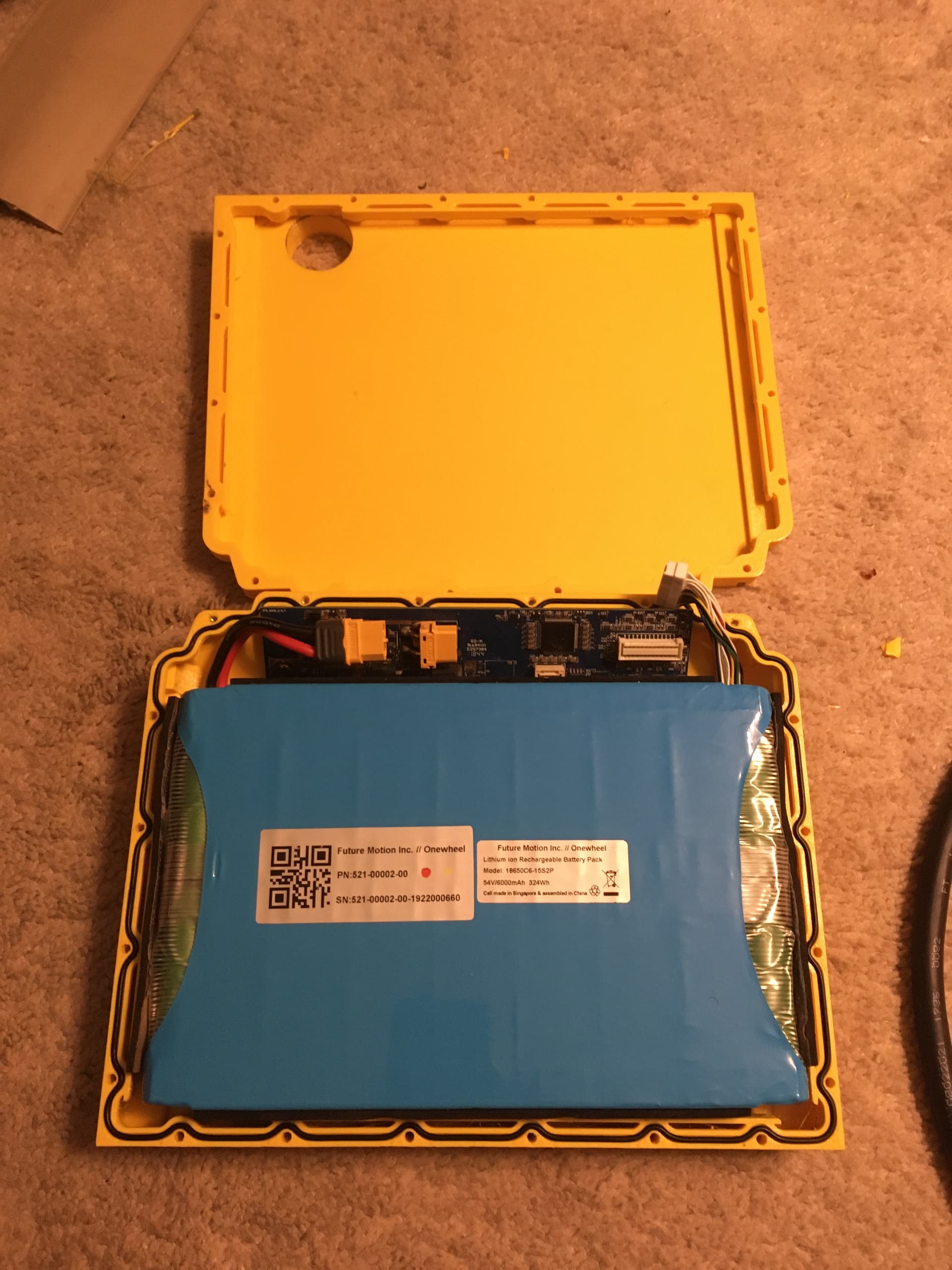
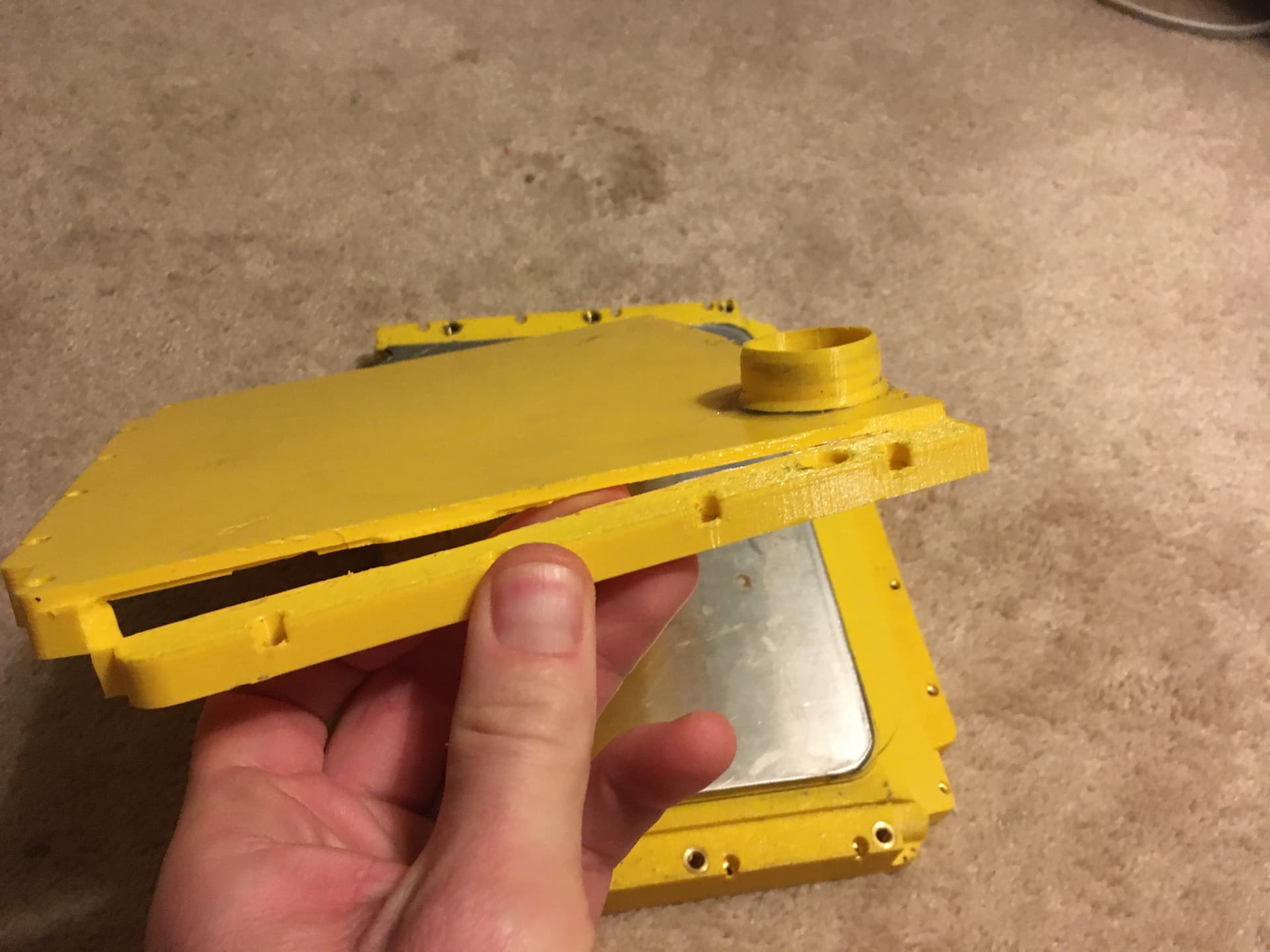
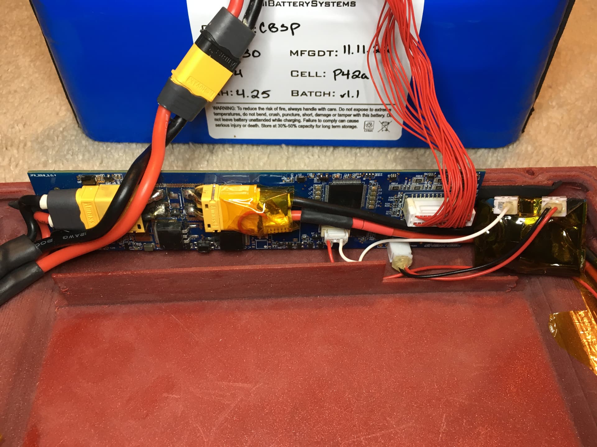
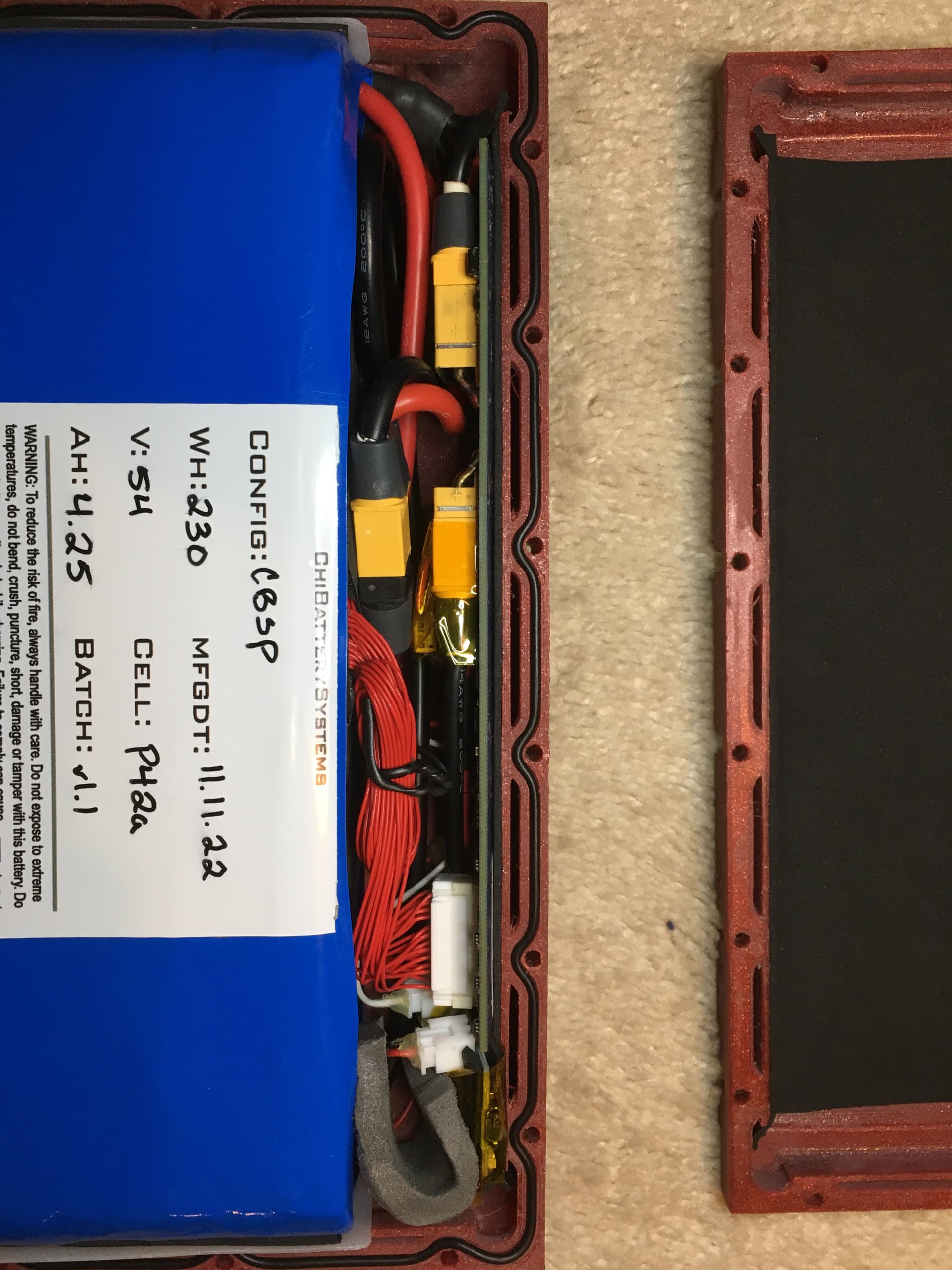
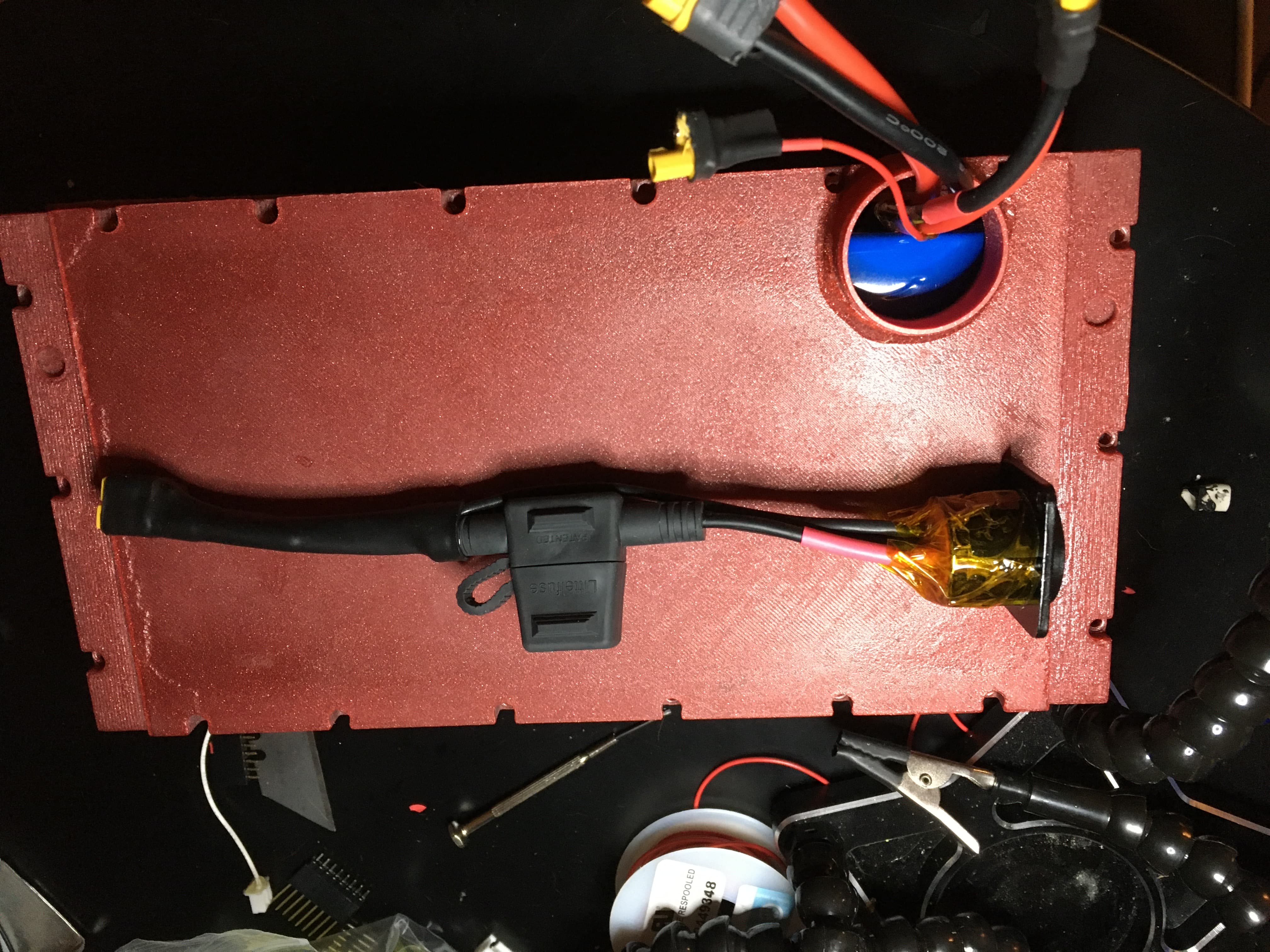
In order to facilitate this connection style I made my own battery boxes. Instead of a aluminum lid I split the box in half close to the top. I added an o-ring seal between the halves. My first box is modeled after the stock box and fits that battery well. Here is my first installation. I figured out that this charge cable does not work. The hot signal delivered to pin 1 on the 5-pin GH connector will cause the BMS to latch open until the battery is disconnected. You need a separate wire.
I discovered that 3D printed plastic is not as strong as the injection molded plastic of the same thickness. In order to provide equivalent battery protection as the stock box I epoxied a 1/16" thick piece of aluminum to the bottom.
Here is this box being installed. I had to enlarge the connector box from the pictures above to fit the XT60. Takes more space than you would think. I use a heat shrink boot and a bunch of z-block to seal the wires entering the connector box from the controller side.
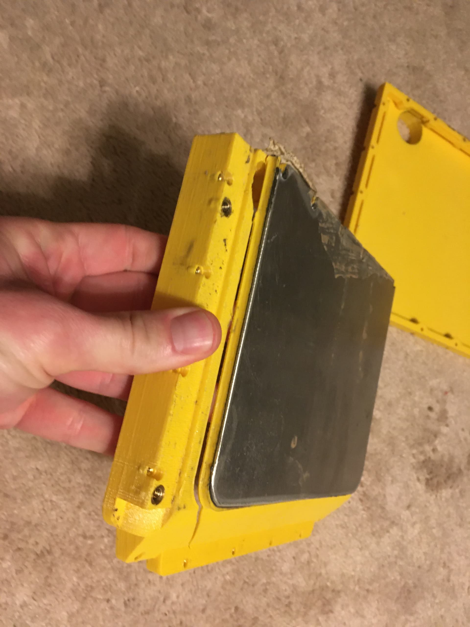
So this box worked for a couple rides. Then I tried to install a CBSP 15s1p 21700 and that cracked it. Bummer.
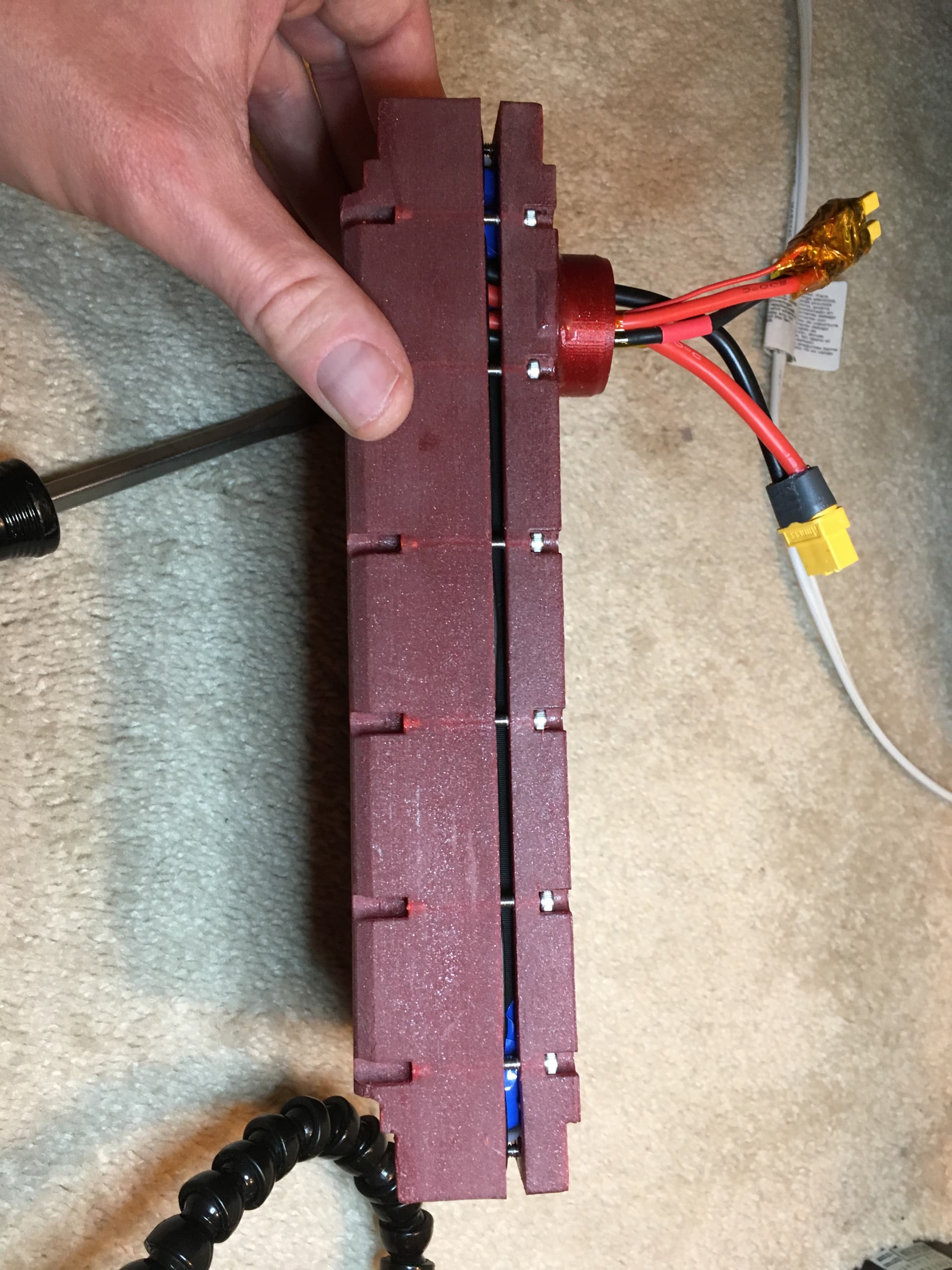
So i went ahead and built a box specifically for CBSP. I maximized the internal height of the box and shortened the length as necessary. For this design I did a salt anneal on the box before adding the heat inserts. A salt anneal remelts the plastic to increase the strength to be more inline with an injection molded part. Here we are ready to install. This time with OWIE.
I added a neoprene envelope around the OWIE chip to protect it a bit. I also added a piece of foam to give it some tension to keep from bouncing around. Neoprene foam behind the BMS to protects it from wear. The extra friction from the neoprene and tension from the wires keeps it firmly in place.
Here is how it closes before you have to start applying serious torque to the bolts. A bit better than the standard box.
Here is is all closed up. You can see my charge connector. It is a XT30 with another single XT30 pin to accept the 3rd pin from the charger to power the BMS. I will probably make this nicer in the future.
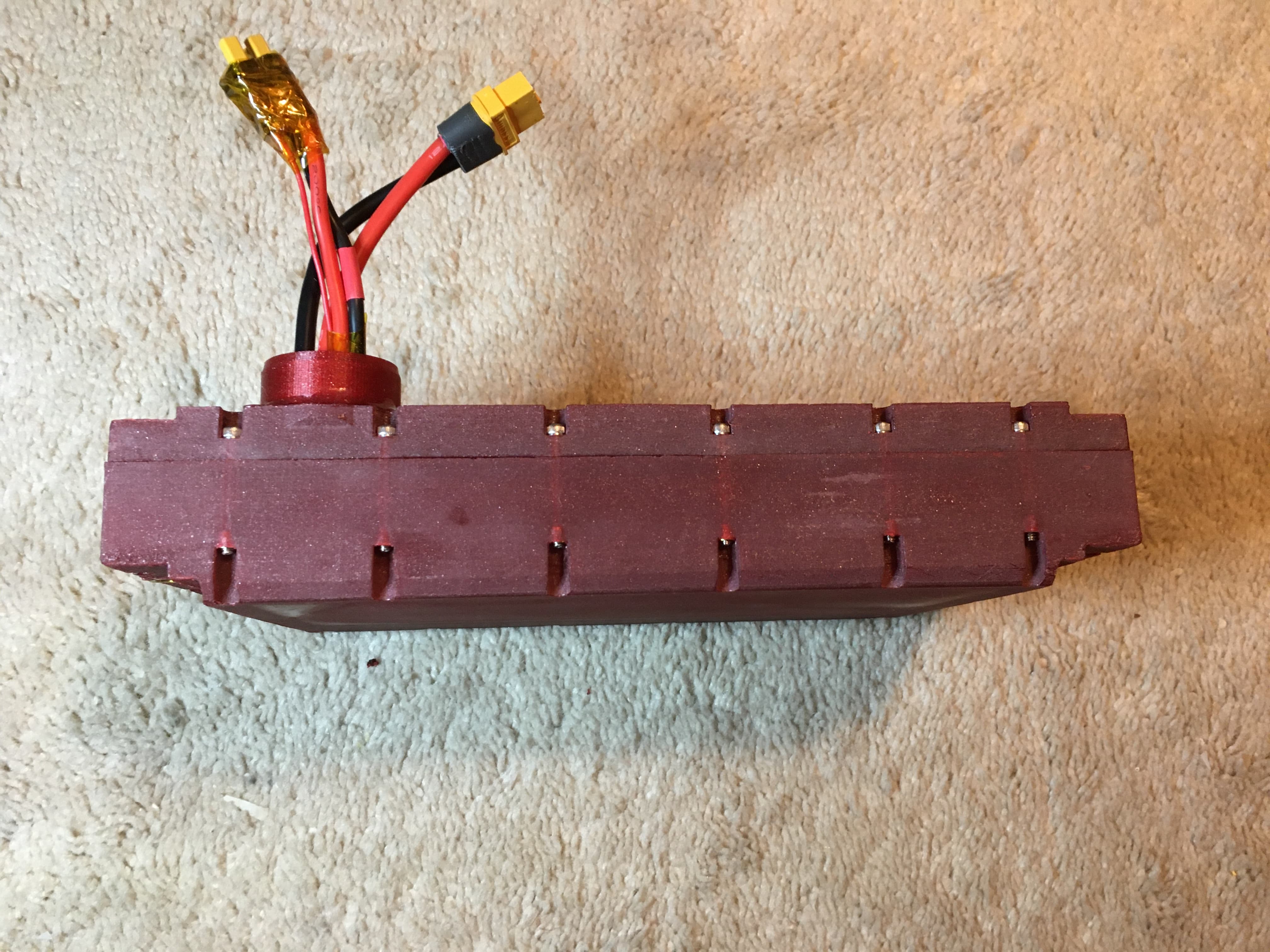
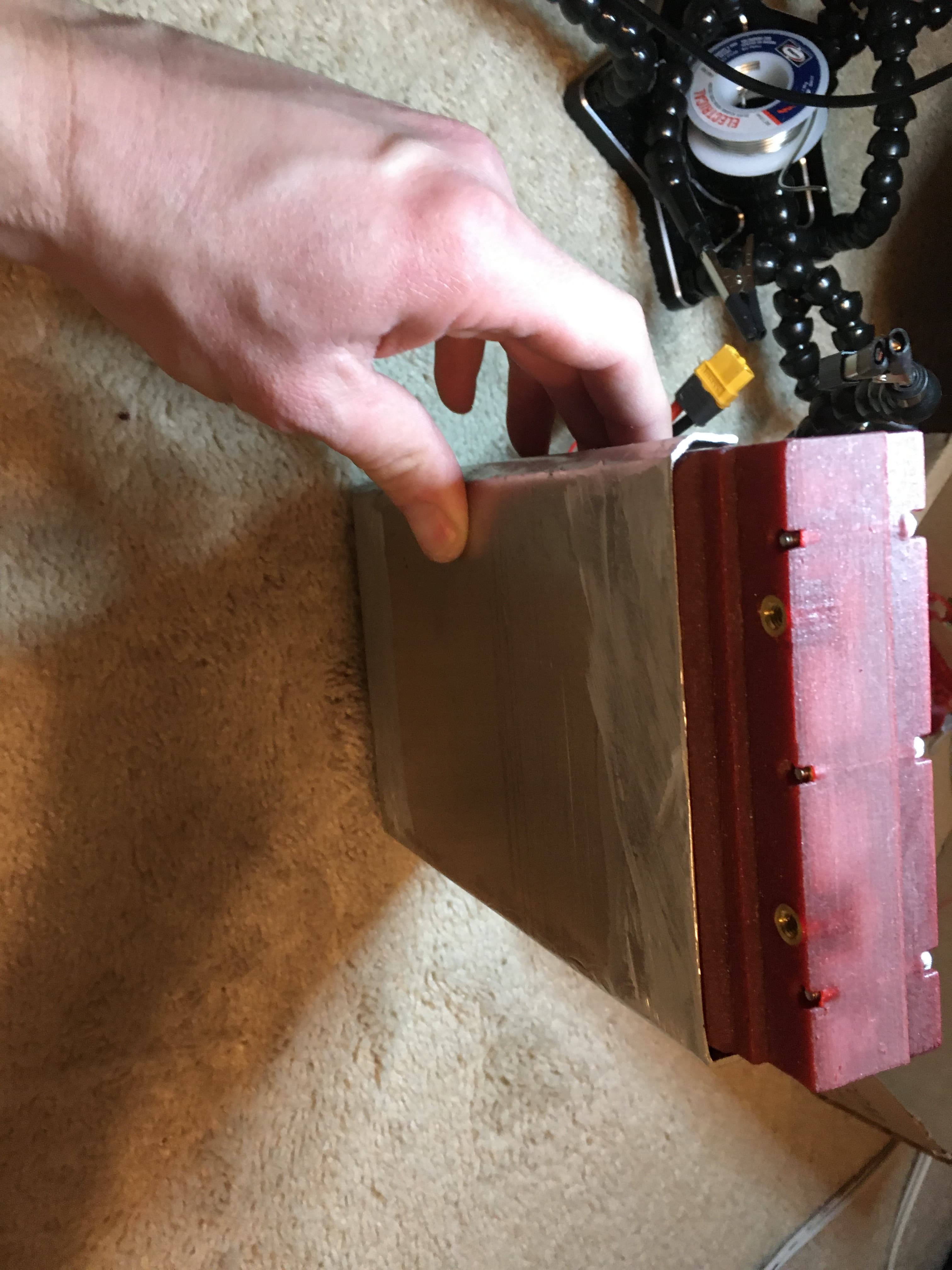
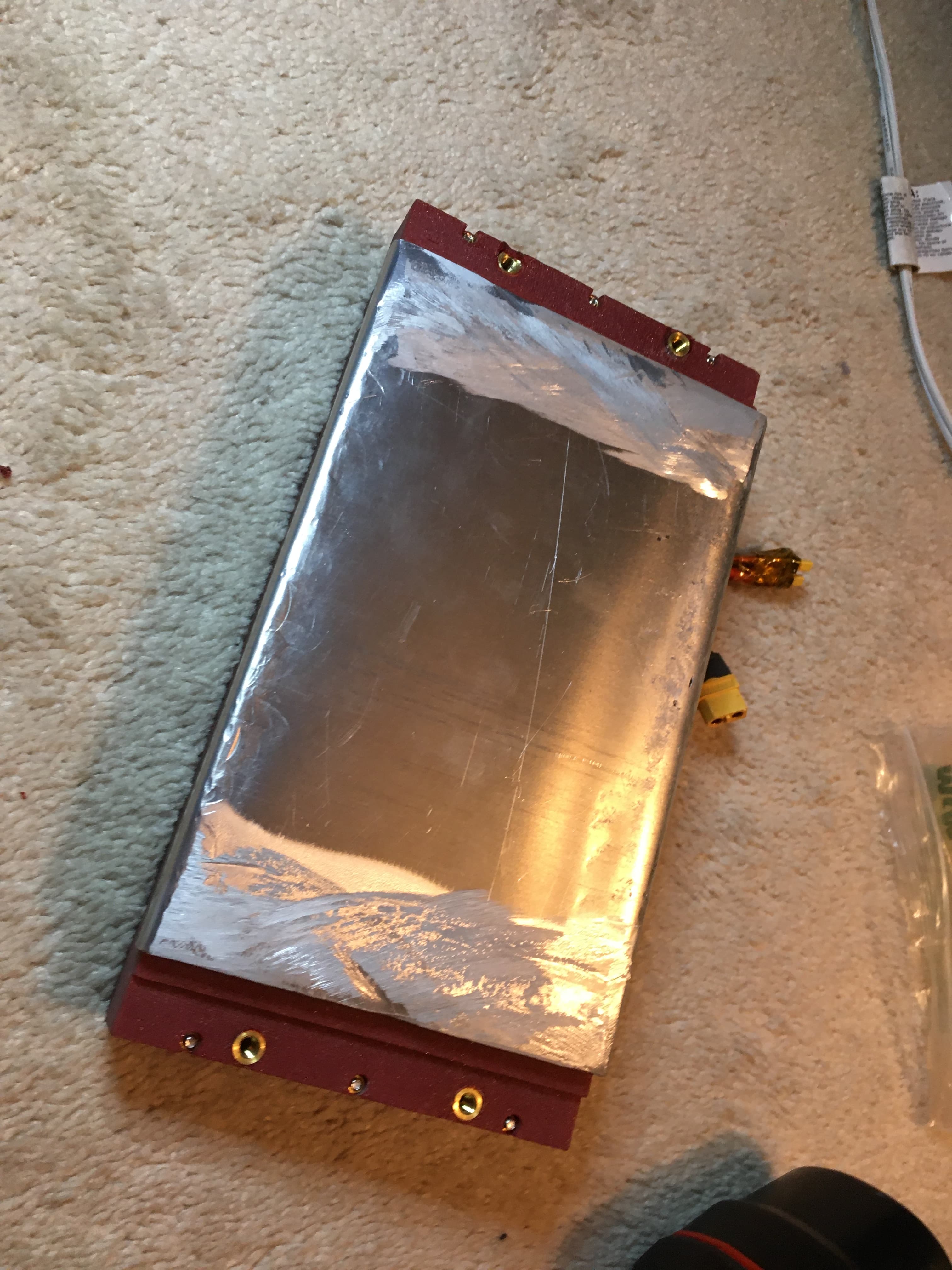
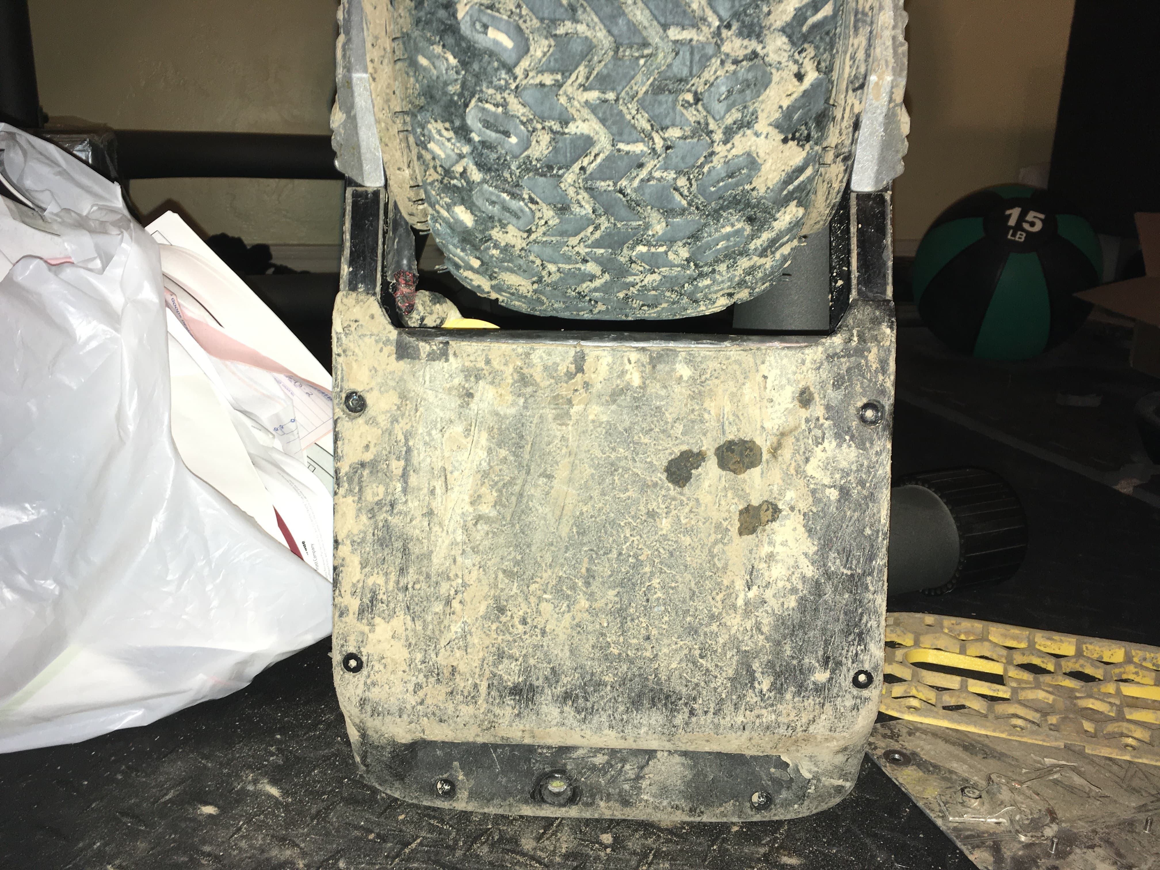
Finally we need some protection for the bottom of the box. I made this from 1/16" aluminum. The bends add a significant amount of strength and I believe this will have less deflection than the stock box. I use double sided tape this time so I can change the shield or the box if required. I’m trying not to commit as hard to this box as the last one since this is still very much a prototype.
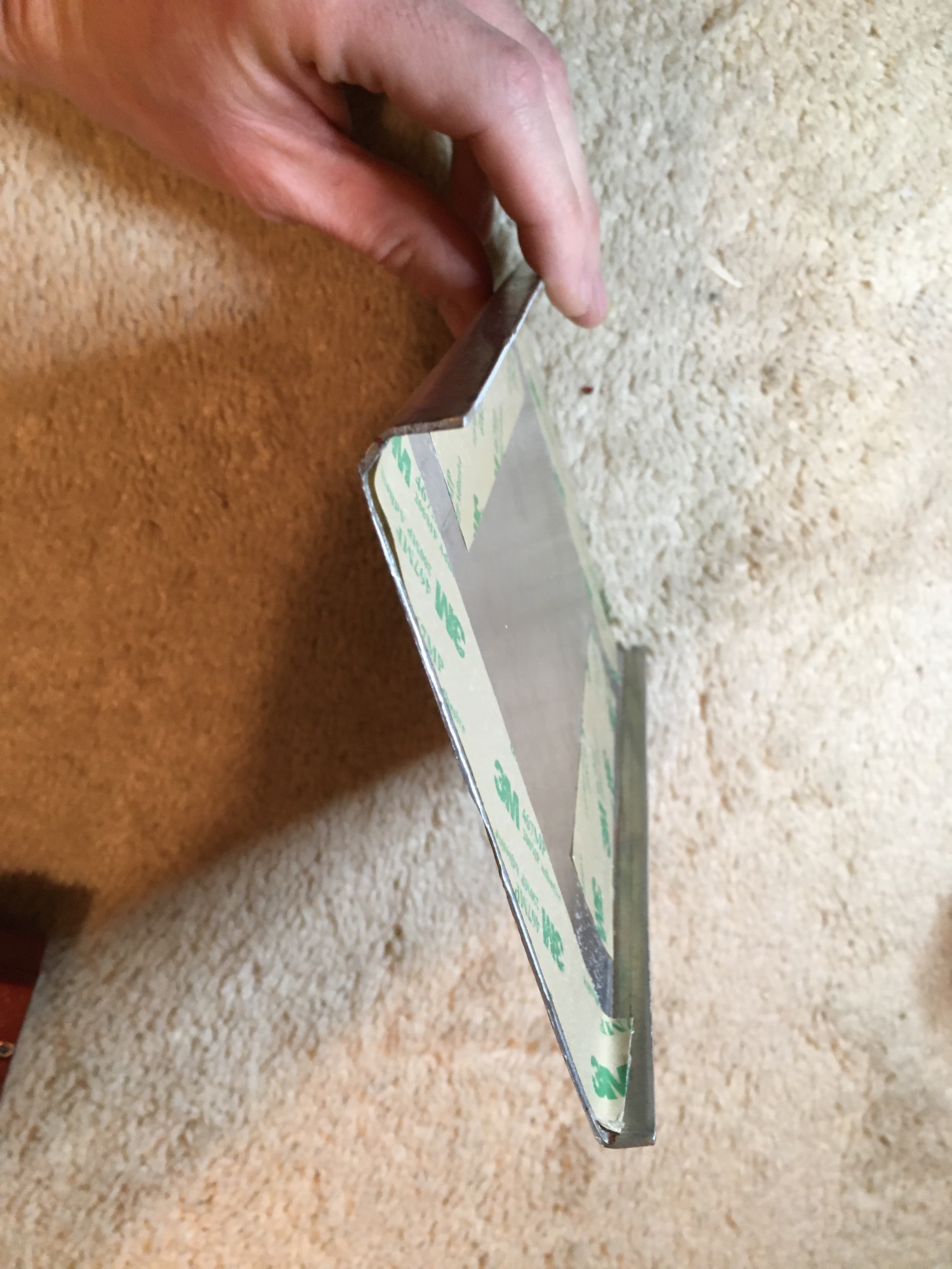
I had to grind down the edges of the shield to avoid interference with the bumper. Only the edges need to be ground because the bumper bows a lot in the middle.
I discovered some interference with the WTF rails toward the front of the box. I sanded this away but I will make the correction for future designs.
Finally here is my charge adapter. I plan to add a diode to this so that it functions properly with my 4206 +XR BMS. 58VDC fuse holder with 7.5 amp fuse. 5 is better but 7.5 is what I had.
I will continue to update as I make changes.
Update 2/6/23:
I have switched from on board FM BMS to external BMS. I was not able to get the FM BMS to work like it is supposed to. You can read about that here.
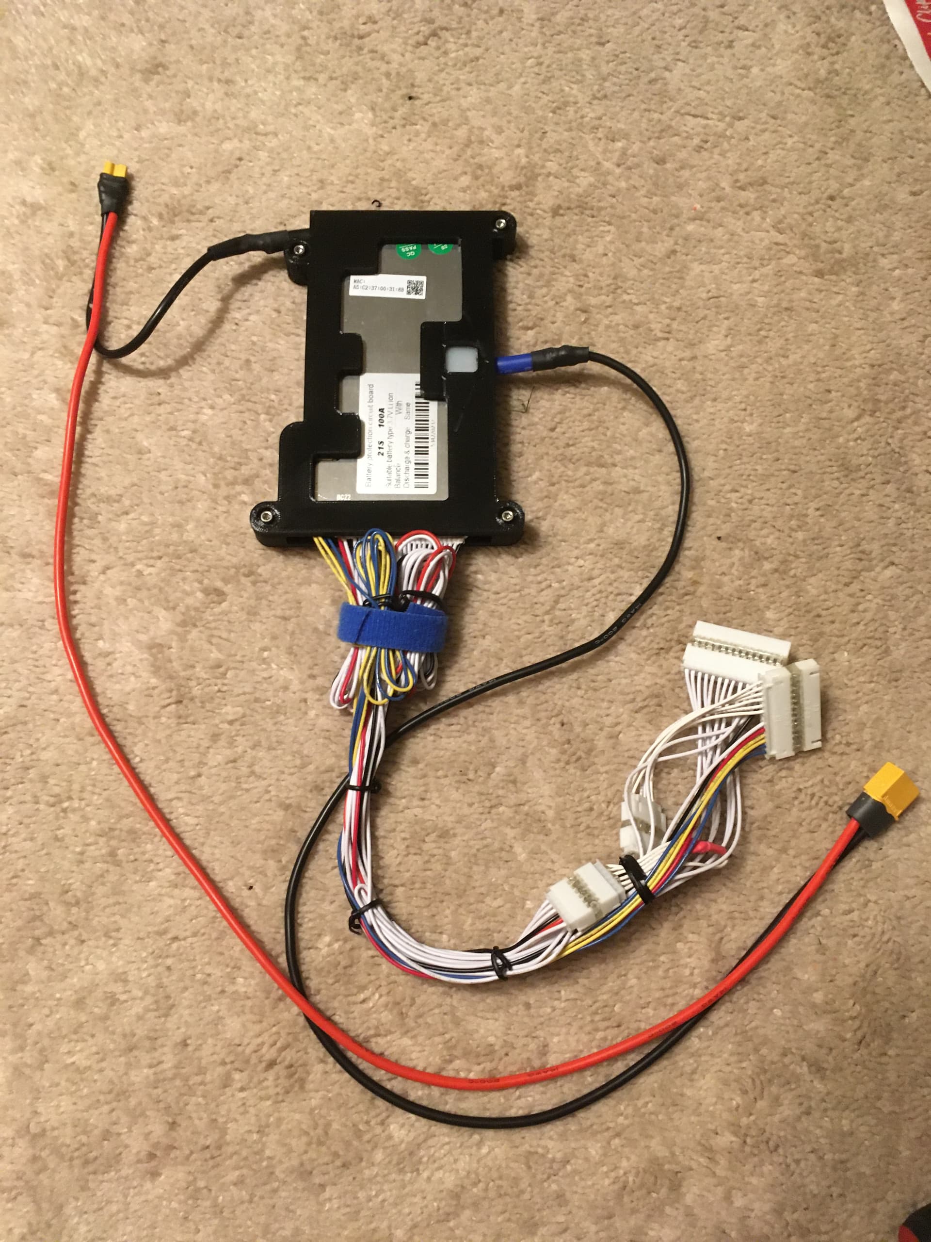
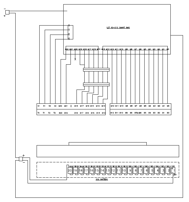
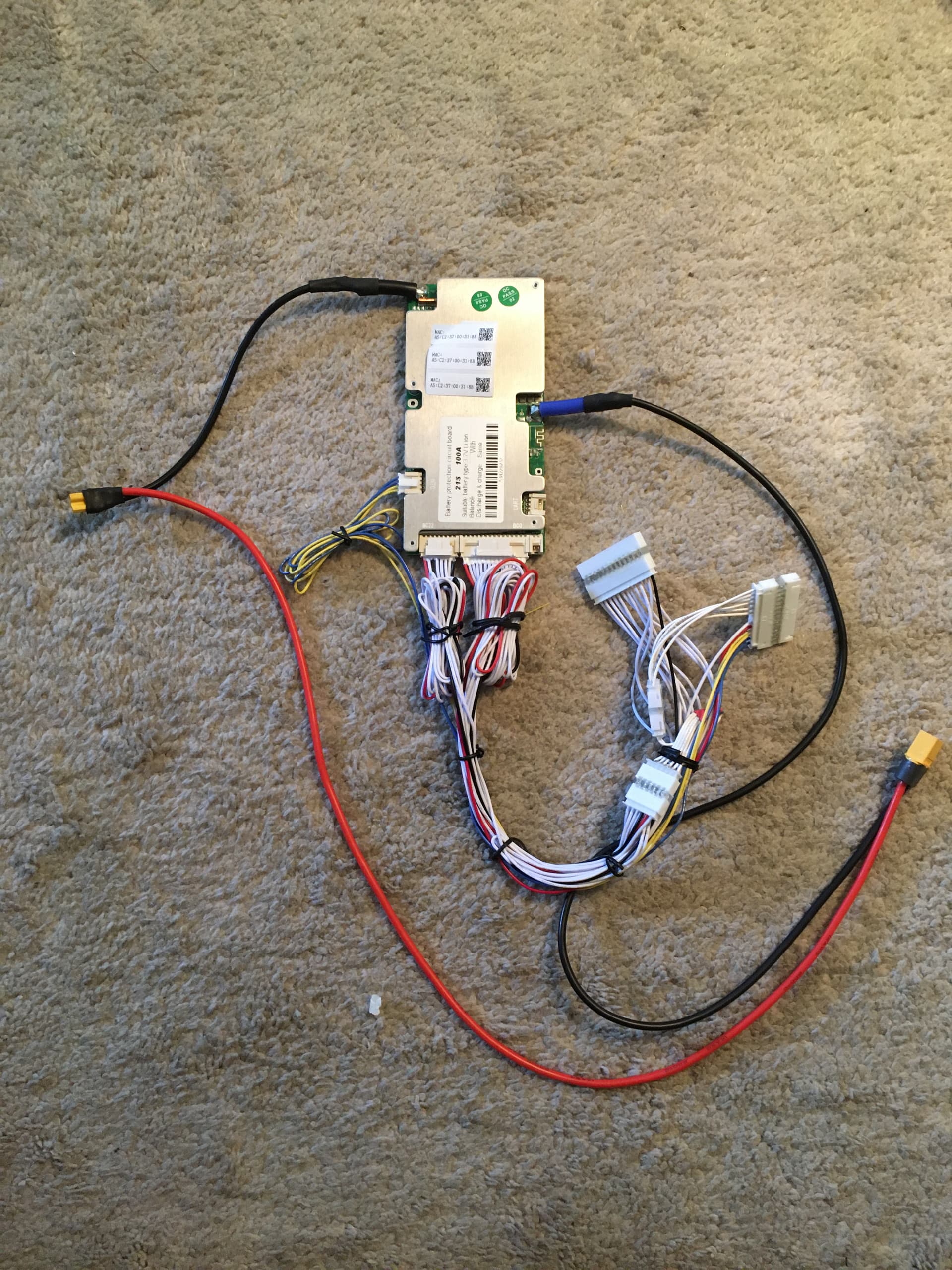
I have decided to use an LLT BMS 4S-21S. I have arranged the wiring so that I can use it for 15S-20S. A small wire section is swapped out for 15S vs 20S.
Diagram for 15S:
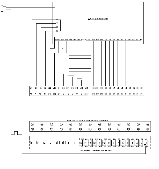
Diagram for 20S:
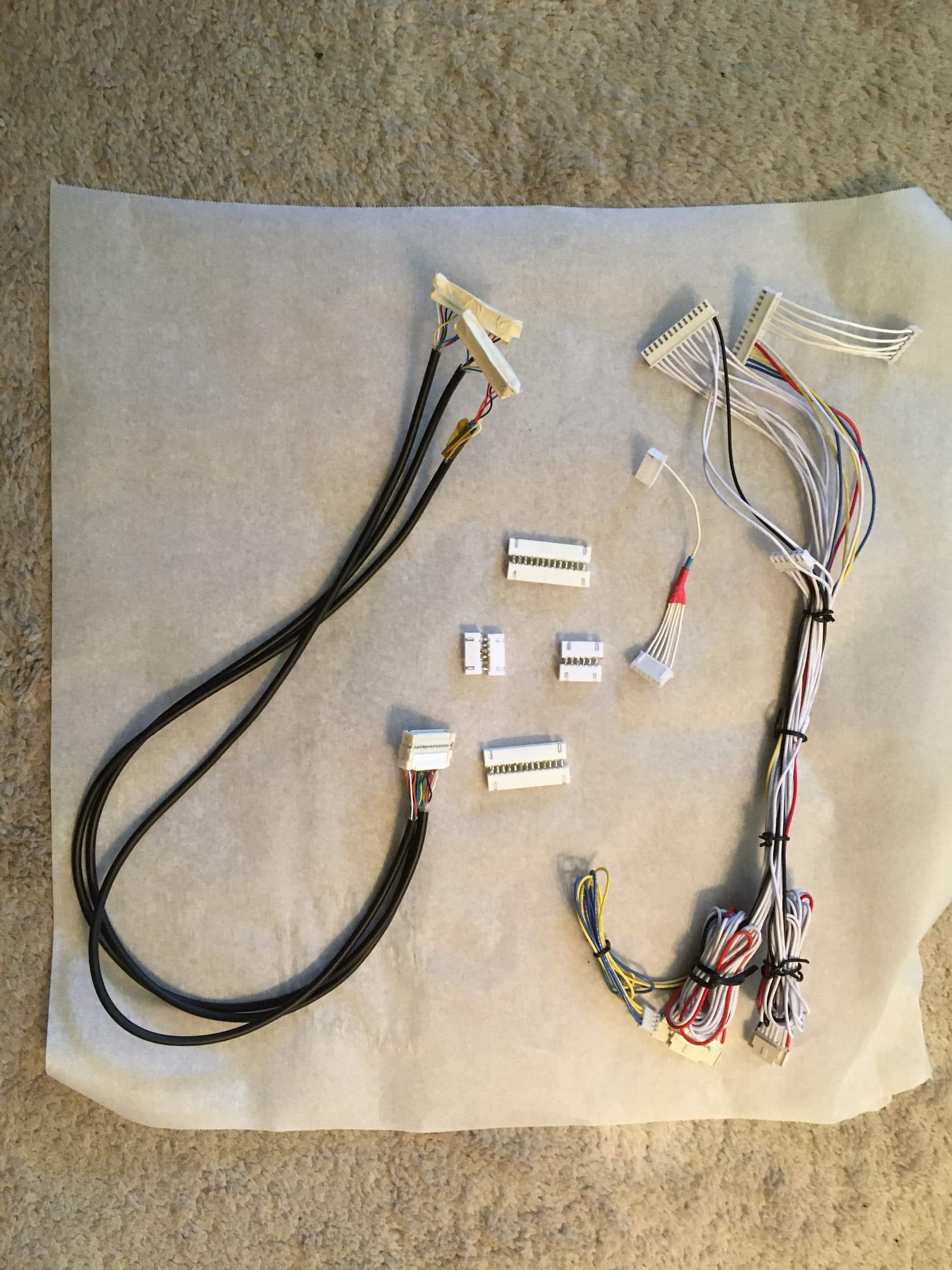
I used JST XH for the intermediate connectors. To attach to an FM battery I glued 2 headers back to back and soldered the SMT tabs together to make a header. I could not find the type of connector that the LLT comes with but I found that this style of connector fits with some sanding. I used premade cable to better organize things in my battery box.
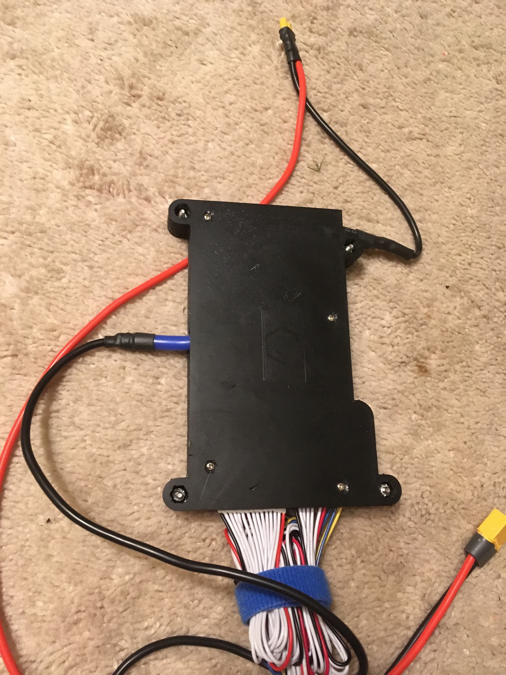
Here is my wiring before I potted everything with epoxy.
Here is the power wiring on the BMS
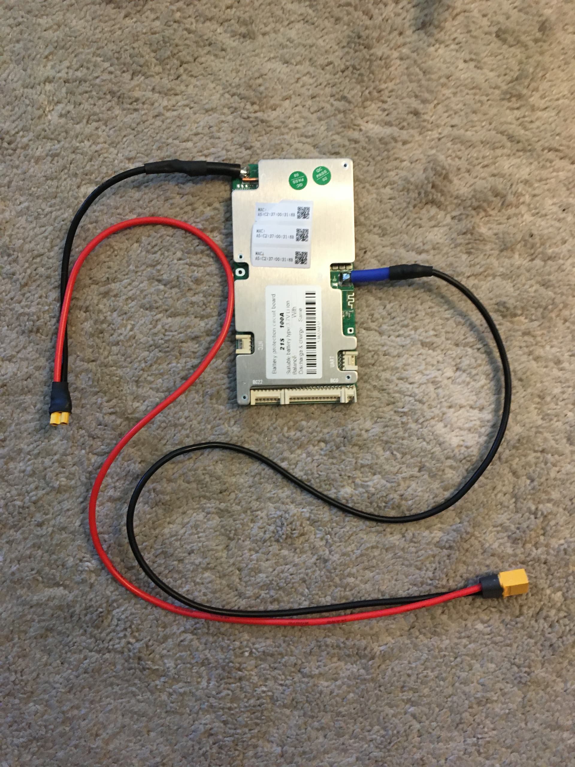
Wiring finished and attached to the BMS
Balance connectors added to the battery box
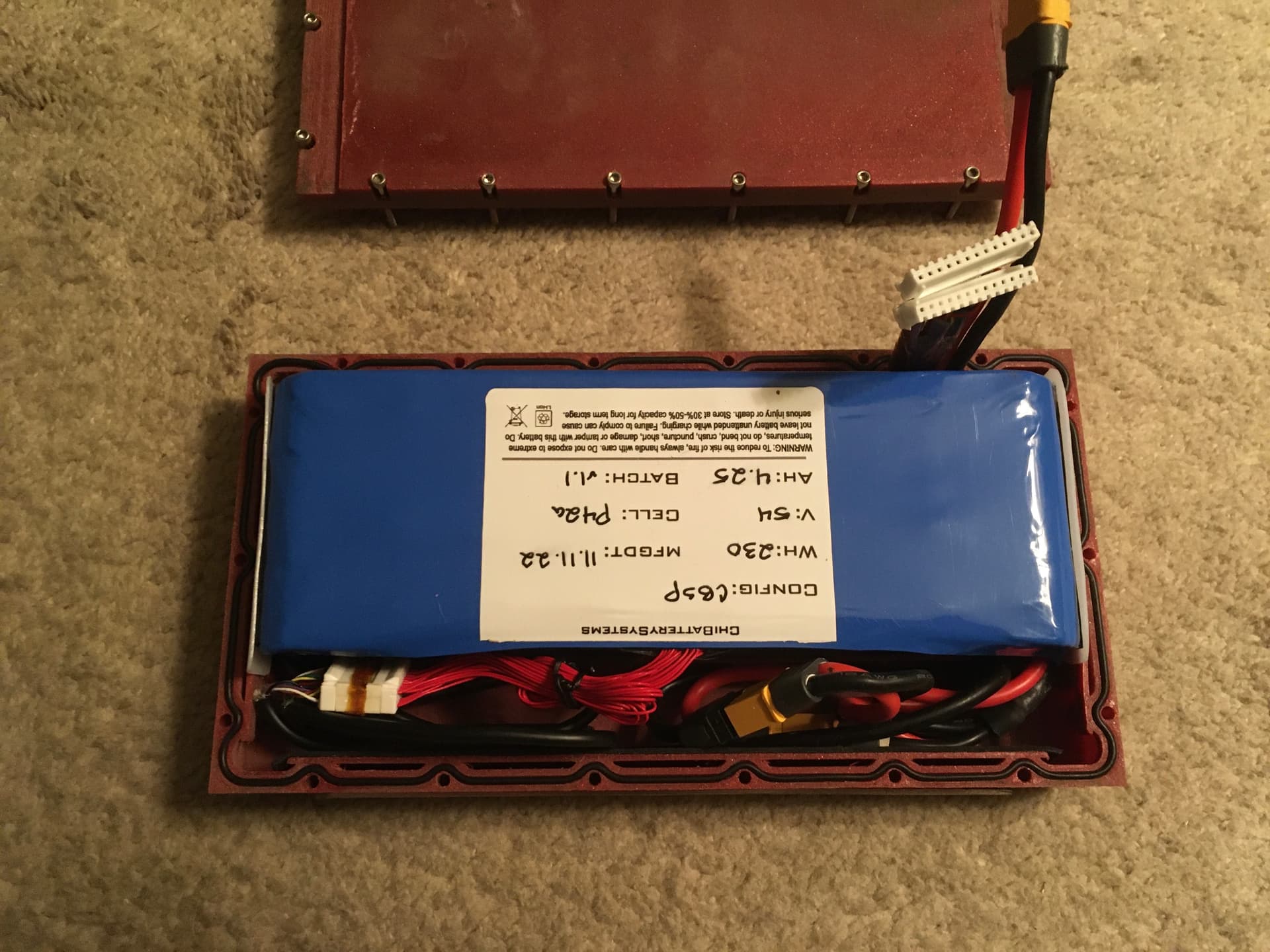
Battery box installed
Made a quick case for the LLT cause I’m probably going to drop it.