VESC - FM-BMS - OWIE Tutorial
Disclaimer: Reusing the FM BMS as a charge only BMS in a VESC OneWheel conversion disables safety features and by going this route you accept that risk. This configuration should allow for reasonably safe balance charging, but there are still risks. Do your own research. The better solution would obviously be a reliable, well built battery pack combined with an appropriate BMS that is capable of communicating with the VESC controller. This is simply an attempt to reuse the FM BMS for balance charging and should not be accepted as a final solution.
Changelog:
- 2022-11-11: Updated method for connecting the FM BMS in charge only configuration that should “in theory” be safer than the previous method.
Table of Contents
- Quick Config/Summary of Options
- Hardware Needed
- Load OWIE FW to the ESP8266 chip
- Installation/Wiring Diagrams (VESC/XR)
Quick Config/Summary of Options
MY hardware/wiring config (Expand)
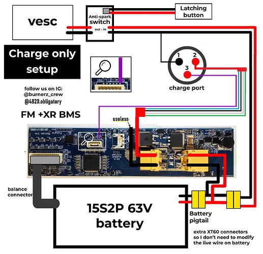
- I am using the standard latching switch with a 10amp diode to prevent power feeding back to the XLR charge pins.
I bridged the positive XT60 terminals on my FM BMS. I have re-run my wiring configuration to match what is shown in the new infographic → Installation/Wiring Diagrams (VESC/XR)- The purple wire from the stock harness connects my XLR positive pins to the FM BMS:
- Connection point 1: Purple wire connected behind the diode (between the diode and the XLR positive pin 2) or connected to pin 3. Not all XLR chargers provide bridged power on pin 3 but the FM Charger does.
- Connection point 2: Future Motion BMS. See infographic.
- I placed my OWIE in the battery enclosure with the FM BMS and CBXR Battery.
- OWIE power is sourced from the FM_BMS 5v and GND Pins
- OWIE Rx hooked up to white wire coming from FM BMS
- In this configuration the OWIE only turns on when the Future Motion BMS turns on due to power on the XLR port (via charge port pin 2 with diode or pin 3) passing voltage down the purple wire to the FM BMS.
Other Options (Expand)
- There is a way to use a momentary switch and the blue wire for discharge BMS config, but I am not familiar with it. Do your own research and feel free to share.
- Place the OWIE in the controller box.
- You could hijack one/two of the small unused wired from the stock harness and use them to run power from the FM-BMS 5v/GND pins up to the controller box or run new wires if all are wires are in use.
Hardware Needed
- VESC Controller of your choosing. I run the little FOCer 3.1
- Any FM BMS (I have only done this on XR, but process is pretty much the same for pint bms)
- 15s (series) battery. Future motion BMS is only for 15s batteries.
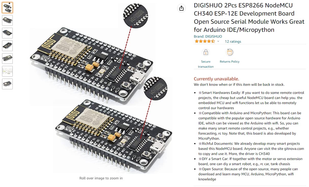
- ESP8266 chip. Can be purchased on amazon.
- Amazon Link: https://a.co/d/4ziJCzh
- Soldering tools
Load OWIE FW to the ESP8266 chip
Option 1 (Windows)
- Download the latest OWIE “firmware.bin” release from github here:
- Download the ‘nodemcu-flasher-master.zip’ from the internet or my google drive link:
- Extract the ‘nodemcu-flasher-master.zip’ to a folder on your PC
- Plug the ESP8266 chip into your windows computer via a Micro USB cable.
- launch the ‘ESP8266Flasher.exe’ executable located in the folder you just extracted. Example:
- C:\Users\yournamehere\Downloads\nodemcu-flasher-master\Win64\Release\ESP8266Flasher.exe
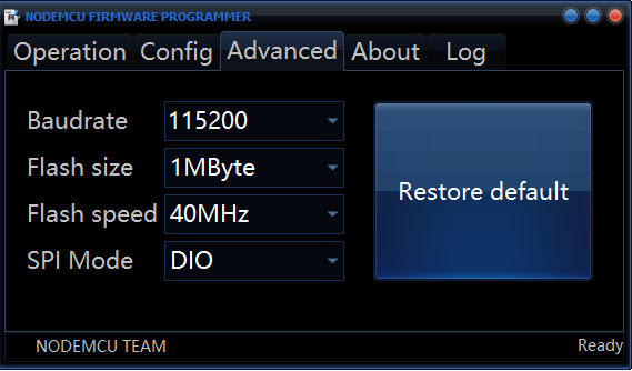
- Go to the ‘Advanced’ tab and set your ‘Baudrate’ to ‘115200’ as seen here:
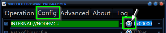
- Go to the ‘Config’ tab
- Click on the ‘Gear’ icon on the topmost line:
- Select the latest OWIE “firmware.bin” file from your computer that you downloaded in ‘Step 1’ and then click ‘Open’
- Click on the ‘Gear’ icon on the topmost line:
- Next, Go to the ‘Operation’ tab
-
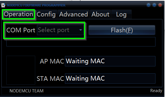
If your ESP8266 chip is properly connected via USB to your computer, then you should see an option to Select ‘COM#’ in the ‘COM Port’ Dropdown: (If no COM port is showing up in the drop-down then it’s worth trying a different USB cable, or looking for drivers. That is outside of the scope of this ‘How-To’ at the moment.)
-
Still on the ‘Operations’ tab, no click “Flash”.
-
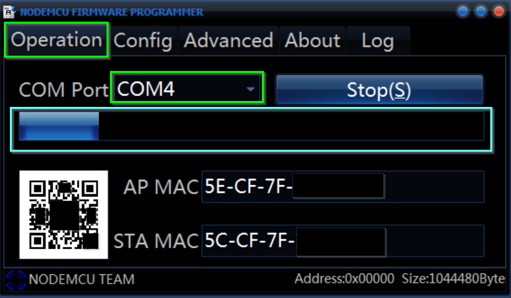
After you click “Flash” the ‘AP MAC’ and ‘STA MAC’ fields should populate and the progress bar should start moving. Similar to this image:
-
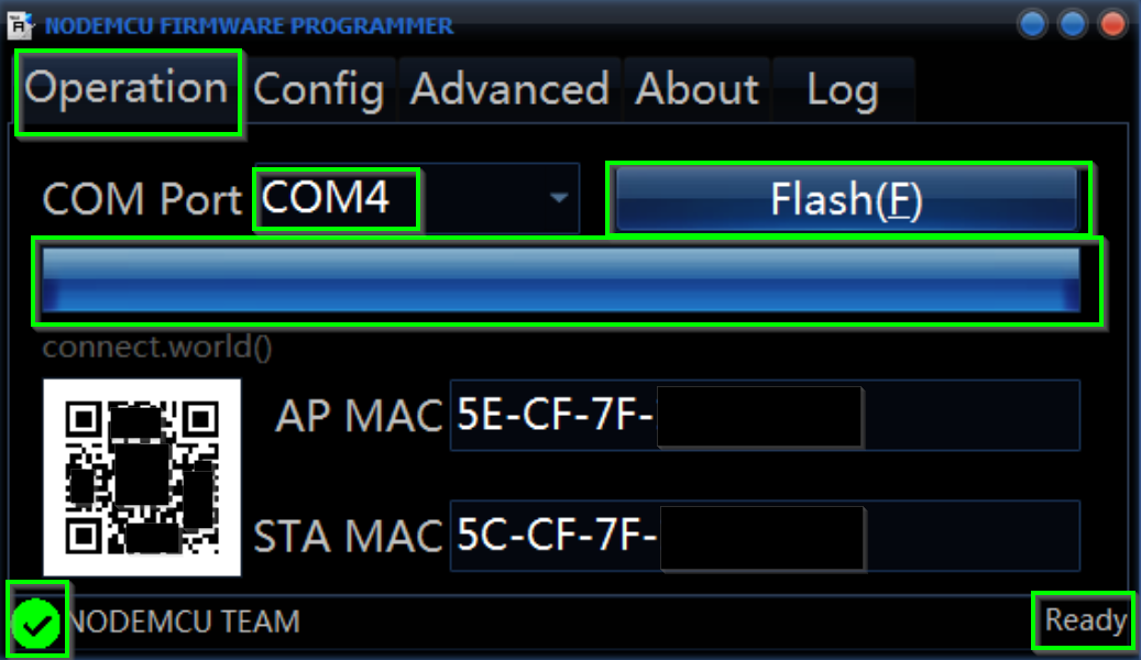
Once the progress bar is all the way across and the firmware flash has finished, the interface should say ‘Ready’ and a green check mark. Also the button will return to saying “Flash(F)”:
-
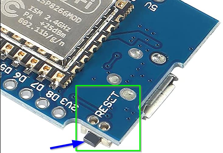
Hit the small reset button on the side/corner of the ESP8266 chip and wait a few seconds for the chip to reboot:
-
You can now close the “ESP8266Flasher.exe” flashing application.
-
Now you are ready to test the OWIE Chip before installation.
-
- Test the OWI Chip before installation
- If you did not hit the ‘Reset’ button on the side of the chip, you can do that now and wait a few seconds for the chip to reboot.
- On your phone you should now be able to find and connect to a Wi-Fi Network named similar to ‘Owie-xxx’
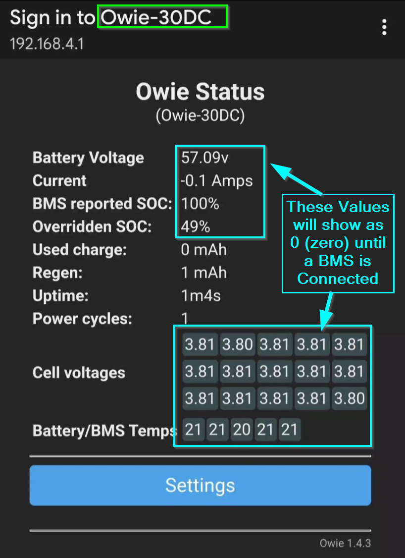
- Once connected you may be prompted to sign-in to the Wi-Fi network or your phone may just redirect you to the Owie page. You should see a screen like this:
- If you see the expected screen then you are ready to install your chip. Disconnect it from the USB port and take the chip over to your BMS for installation.
Installation/Wiring Diagrams (VESC/XR/OWIE/FM-BMS)
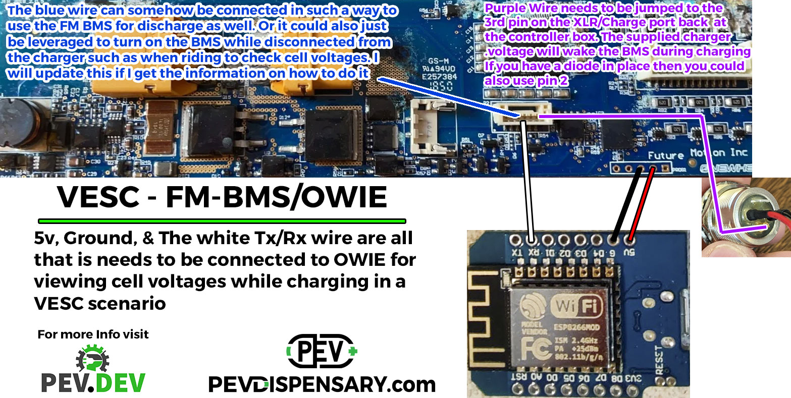
Addtional Wiring diagram provided by @Haverr4 & @OMOT :

Acknowledgements
Thanks to @Haverr4 & @OMOT for their contributions and explaining to me why this is the better option as it still allows the FM BMS to cut power to the battery when charging.
- See @Haverr4’s post below for the original diagram on wiring up the FM BMS:
GUIDE: How to wire FM BMS as "Charge only" for your VESC