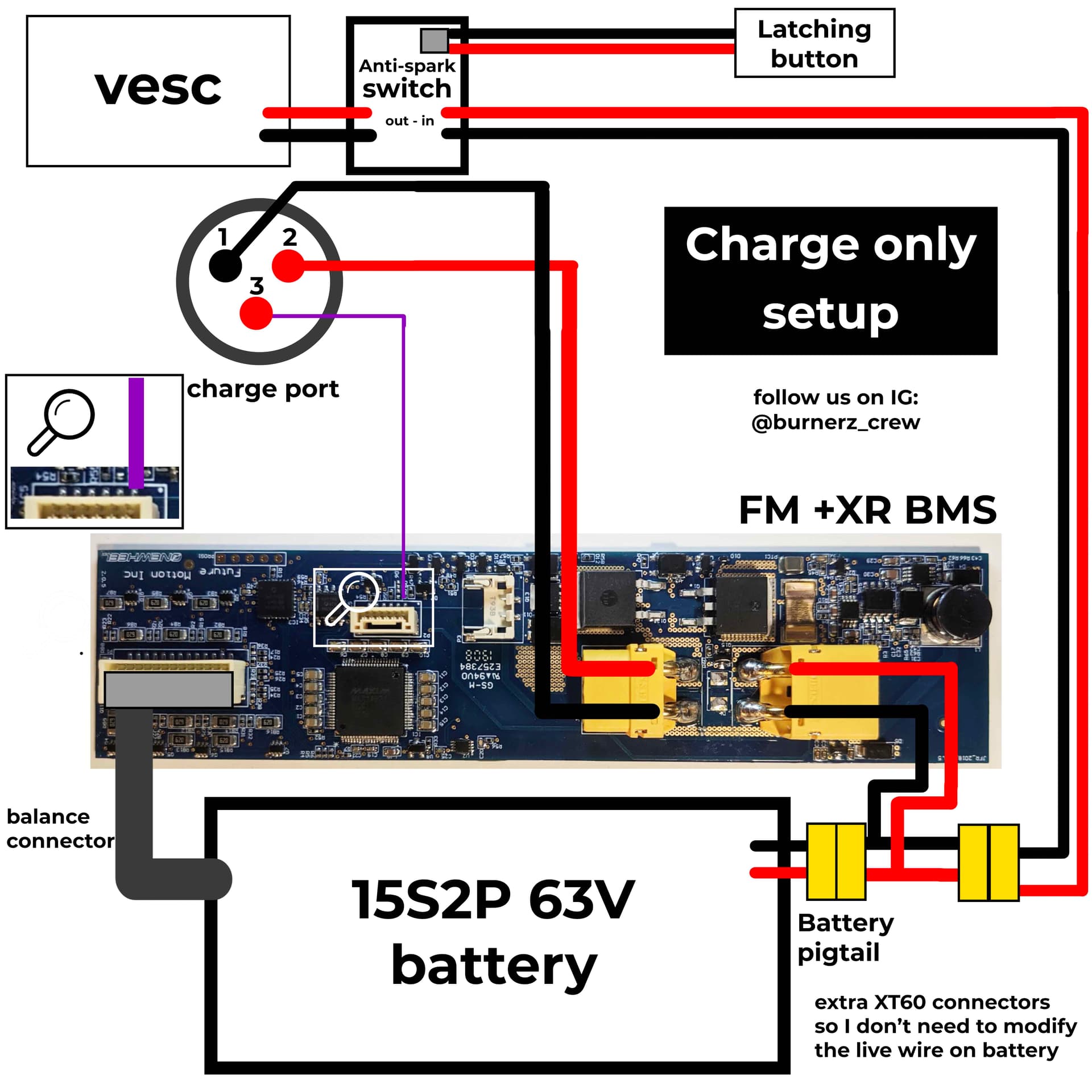
I used a Flipsky VESC with Antispark switch
Special thanks to Oliver Motlik for helping me to make this guide.
Special thanks to Oliver Motlik for helping me to make this guide.
WTF!? That’s it? So easy. Thank you so much for posting. Since pin 2 and 3 on the charger are the same you could just solder in a wire on the board instead of adding the purple lead I believe.
Funny that I actually just found this post and it’s also provided by Oliver Motlik. He just explained to me in detail what exactly charge-only means and when it’s required and/or recommended.
@Haverr4 would you be able to add it into your Guide once I am done with translation? It was via FB chat and in German.
Or maybe @pevdevadmin can make your topic into a Wiki? ![]()
I was curious about this as well. I have to fully test it though.
At what point would you reverse the polarity if using a FM battery? Would it be where the XT60 is connecting to the anti spark switch?
I see the diagram in the OWIE guide is different, can you update this guide as well unless there’s a reason this one is different that I am missing?
Yeah… The one in the OWIE tutorial has been updated to reflect using the stock FM harness. This one is more general. I would probably interpret this one as using a non-FM harness. But also the one in the OWIE guide does away with the charge side negative wire and shares the charge/discharge negative as it’s bridged on the BMS anyway… Not sure if it’s worth having two… or if this one should just be updated. Also I think the “Anti-Spark” switch may be optional/user choice depending on the setup.
This what i’ve noted as well. From what I understand the Anti-spark switch is not necessary providing your controller has an integrated witch AND you are using it. (ie lfoc3.1). I think the different diagrams are necessary - one for modifying stock harness and one that’s more general for those who want to run their own wires.
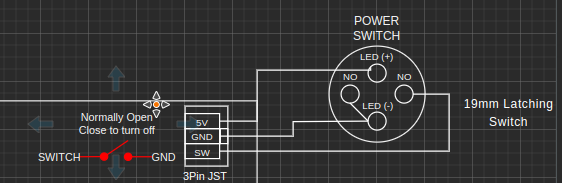
Ok couple questions Does anyone have the link to the anti spark switch- is it even needed?. And in the diagram is the latching button the same as the on off button. and finally is a 15S2P the stock onewheel battery? Do i need to chip the BMS? or is that just extra? Super new to this process. thanks for the patience.
Thanks for the helpful answers!!!
The reason is because, the other diagram is for stock harness, this one is for a custom harness.
I would add the stock harness picture too, but I can’t edit this post for some reason. @surfdado can you check on this?
ok: it’s a Wiki page now, anyone can edit
Im just getting now to wire an FM bms. Minimal wiring to the front and custom “harness” Could in this case the purple wire from the bms not be hooked up to the charge positive right next to it? This would mean only 2 power and 2 charge wires running to the frontside?
I’ve looked over the wiring and did the flash for the esp. Got the esp to establish a wifi and show the balance firmware but not getting any data from the BMS. I’ve tried a few things but with no luck.
Screen shows a connection time. with no amps no cell data.
I have a FM 4209 BMS and following this guide.
Wondering the same thing
I completed this wiring in my board and plugged in my stock XR charger while monitoring the battery voltage. The voltage went up to 64v. I expected it to stop at 63v. I disconnected the charger and observed the voltage drop back down. In this configuration will the charger or stock BMS not automatically stop charging at 63v?