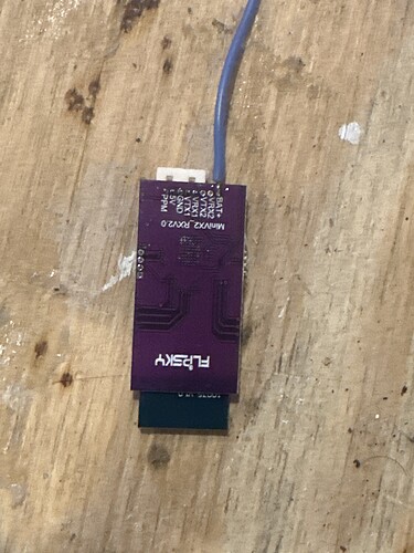
Do you have a picture of the completed install? It mentions in the bkb setup to put the receiver into a 3d printed case, did you do that? Is there room? If so do you have the STL?
I dont have a picture, it should just be secured wherever it fits best in your specific setup, preferably away from the motor phase wires. The remote should have come with a 3D printed enclosure, if yours didn’t I would reach out to BKB.
Ok great, I just didn’t see it in the “what’s included” on they’re website but hopefully. Thanks
helpful info for anyone using ubox80v100a and flipsky vx4 remote (probably applies to other remotes too):
- You can use the bluetooth nrf module and the remote at the same time. Plug your remote module into the unused pins in comm (the footpad port). After connecting 3.3v, adc1 and adc2 to footpad, you should still have 5v, gnd, rx, and tx left in the comm port. Those go into the remote.
- make sure you plug remote TX into ubox RX, and remote RX into ubox TX. If you plug TX into TX and RX into RX, it won’t work.
Do you know what the original baudrate should be? I just want to double check that I didn’t change anything I shouldn’t have. I have the bkb voyager and can not figure out why it’s not working. I triple checked the wiring and it’s 100% correct but I’m not even getting any voltage reading on my remote. Do you have a cheat sheet of what ever setting should be on the remote? As far as I can tell it’s set up exactly how you said.
What? Do I have to explicitly swap RX and TX the wrong way with the Flipsky? That would explain why mine isn’t working, but I would never have tried that if you hadn’t told me. Is that strange wiring documented somewhere? I’ll give that a try asap and let you guys know if it helped.
It’s not “the wrong way,” its just how TX/RX works. Slighter counter intuitive compared to other pinouts for sure, but the T stands for Transmit and the R stands for Recieve. So the VESC has to recieve (RX) what the remote transmits (TX), and the remote has to recieve (RX) what the VESC transmits (TX).
Grain of salt, this is assuming this actually works which i cant double check right now haha, but the logic makes sense to me.
I’m using the flipsky vx4 remote connecting it to a floatwheel. Floatwheel has an open ppm port on the controller. The flipsky receiver has a blue wire soldered to the “battery +” pin. It seems you only need the 3 wires for ppm, so what I’m asking is do I just cut that wire off? Is there any advantage to hooking up to battery +? I did cut the wire off of one using uart and it was fine, but wondering if ppm may be different.
Bat+ is for UART so unusable on Floatwheel (must use PPM) since Flipsky VX4 LCD will only show battery level on a UART connection. I desoldered that cable,
Not if you’re using Avaspark RGB since it will take up those pins. VX4 will need to use PPM which is a bummer since you don’t get any of the extra data onto your LCD screen.
Problem solved!
VESC Express CAN bus Bluetooth module
https://avaspark.com/product/vesc-express-can-bus-bluetooth-module/
But not exactly for Floatwheel. No CAN port and only some ADV/ADV Pros have CAN bus chip built in. BTW if you have a Floatwheel, read this:
https://www.reddit.com/r/FloatwheelTeam/comments/1awgzyn/floatwheel_remote_guide/
