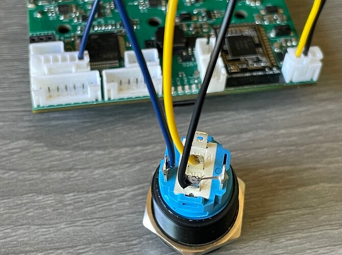
This picture shows exactly how to wire a power switch, pick one that’s 19mm and intended for the lowest voltage you can find. This one is for 3-6V:
The black wire connects both the common pin of the switch and the minus pin of the LED, going to GND on the VESC.
The yellow wire is the switch pin, I’ve connected it to the normally closed pin
- Normally closed: switch will be out when the LFOC is on
- Normally open: switch will be in when the LFOC is on (more natural, but has downsides*)
The blue wire is for the plus pin of the LED. I’ve connected it to PB12 on the LFOCv3 where it’ll be firmware controlled (requires my firmware), but it can optionally go to the unused pin on the 3pin connector, then it’ll work with any firmware and will be brighter, because that’s a 5V pin.
*Downsides of wiring the button the “normal” way: if your latching button breaks or comes undone due to a strong jerk (big drop or bonk) the LFOC will turn off!! Happened to me once, had to duct-tape a little pebble onto the switch to force the board on and finish the ride
…
