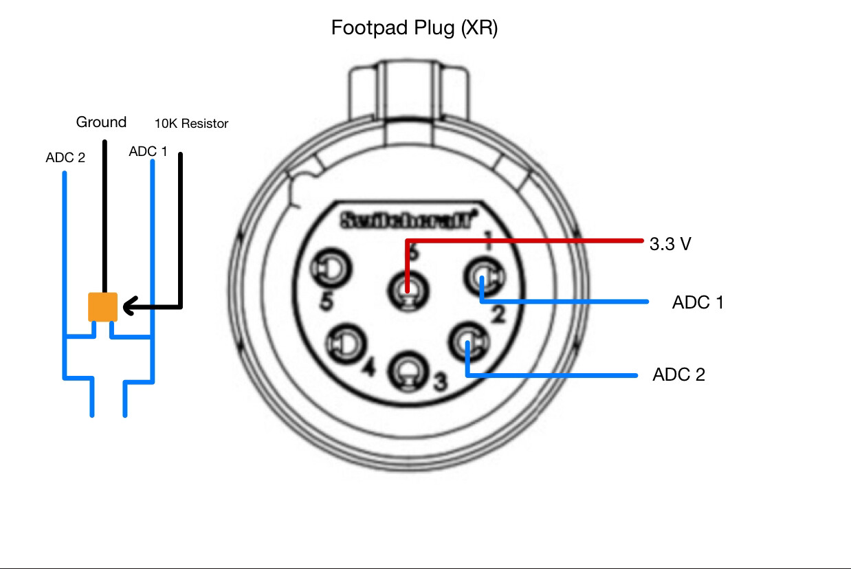
This is the wiring diagram for the XR footpad. This should allow you to repurpose the stock switchcraft connector and footpad connector without much trouble.
This video should help you on how to desolder the footpad connector from the stock XR controller.
This is from the front view of the connector, and the pins are numbered on the connector.
2 Likes
Thanks for the diagram! Helped a ton when converting my XR.
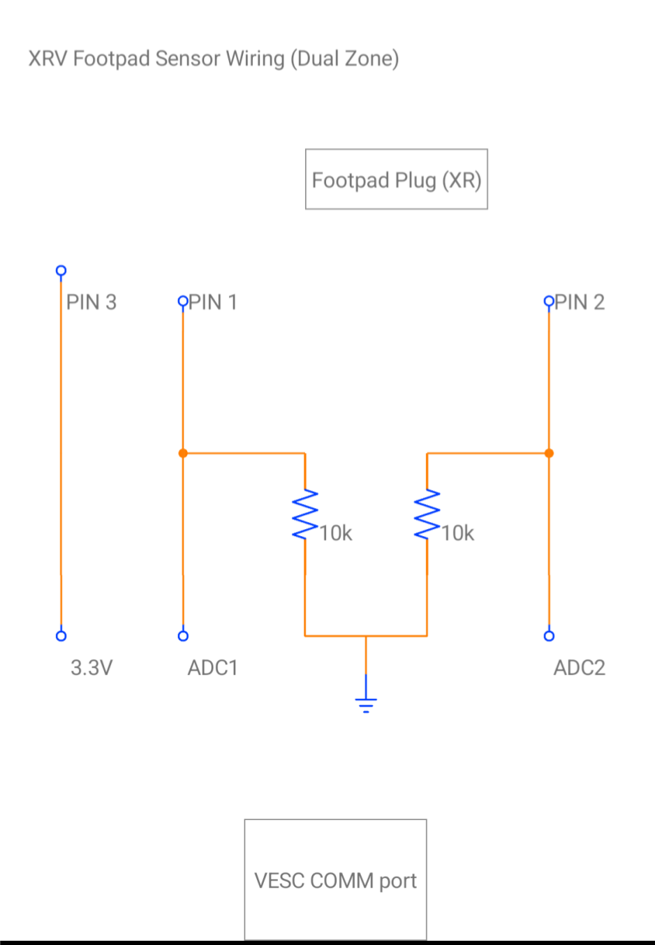
I was initially confused by the ADC to ground drawing on the left, so I went ahead and redrew it as a more traditional electrical diagram, hoping to help out any other vesc newbies that stumble across this in the future.
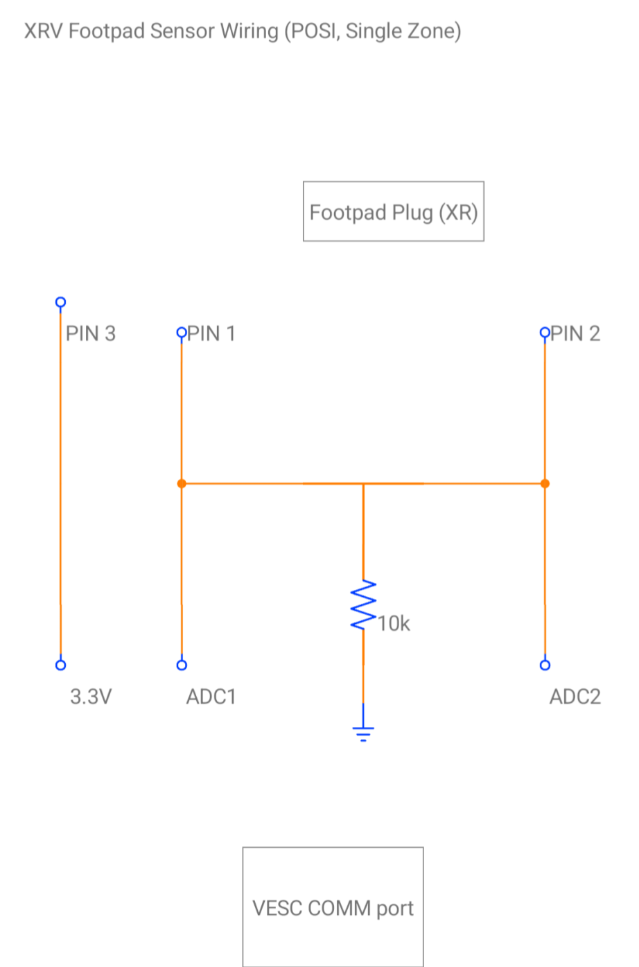
It’s worth noting that the above diagram is POSI’d, single zone. I’ve included wiring diagram for both single and dual zone. Whatever your little vescy heart desires.
1 Like
And the single zone wiring diagram
1 Like