Anyone have this? Specifically, if I’m looking at the molex connector end, which pin is the purple wire, which is the blue, etc.
Edit (surfdado):
Here’s what I found out:
Connectors
Full kit: BMS Wiring Kit for 15S OneWheel Pack – Battery Broker PEV Parts
DIY: You need a female 26-pin JST ZPD connector and GH crimped wires
For the PCB (if you’re making one) you need:
Wiring Diagram
TBD
In case anyone else comes here looking for a pin out, here’s a link to a great one Redirecting...
Looking for the same answer. My setup: ZBMS, 18s2p 50s 75.6V battery. Putting an XT60 on a Plus harness for discharge path, but need to determine if remaining small-gauge wires from the harness are suitable for dedicated charge circuit (XT30) from the XLR port. Reserving 4 wires for the taillights, I have 4 wires to work with on the FM harness, and am wondering if there’s a popular way others have done this that I should follow.
The 4 wires (and FM pinout) are White (BMS A), Green (BMS B), Blue (PWR), Purple (XLR3+).
Any advice would be appreciated.
did you end up figuring this out? i’m trying to use a stock XR wiring harness on a Ubox 85 JWXR SSBMS build
1 Like
Yes, it’s been solid. I recommend using a fuse on the charge leads, though, so it burns out before the wires do. Here’s an example with a different controller: Build Guide with Thor300, Superflux, Funwheel Controller Box, 20s2p split pack, Xlite BMS, and Lights - #3 by goto11
assuming the post is undeletable, which it isn’t, doesn’t contain FM proprietary info, which it does, and that FM is a chill company who doesnt c&d/take down or attenpt to prevent people from replicating their products, which they aren’t/do/do, and that facebook’s link structure will never change forever, which it will:
could you do a “for anyone coming to find this info that cannot accss the private facebook group” follow up? this information should be readily available both on pev.dev and several discords instead of languishing behind a meta log in wall. thanks in advance
Yea I was looking for the pin out for a stock XR harness BMS/charge wiring to a ssbms as well, would be awesome if it was right here!
as luckk would have it homie in addition to being someone who whines about other people not having already solved problems he didn’t know he was going to have, i also am the change i wish to see in the world
ill hit you witg. the other side of the cable tomorrow,
but that’ll get you started
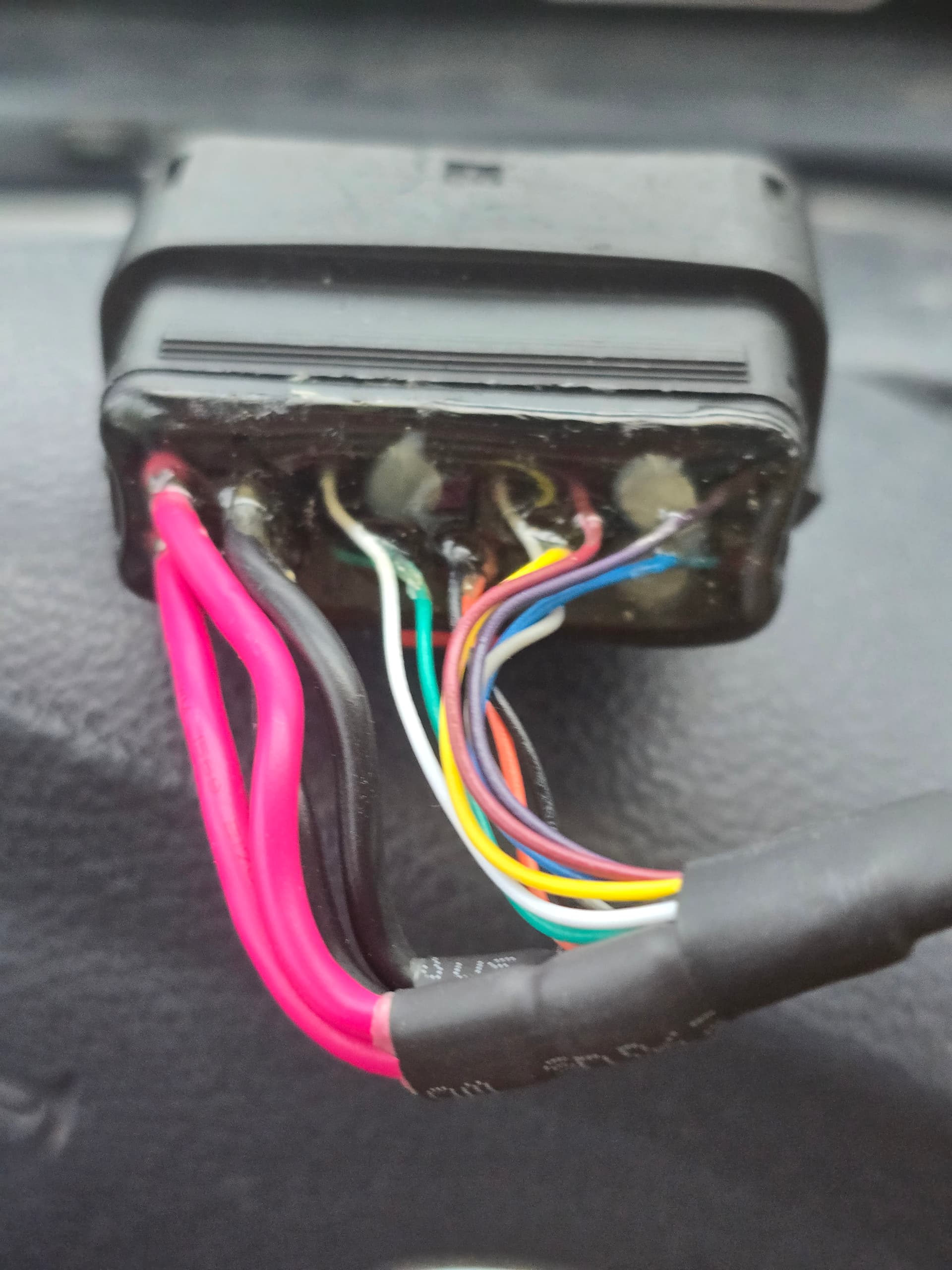
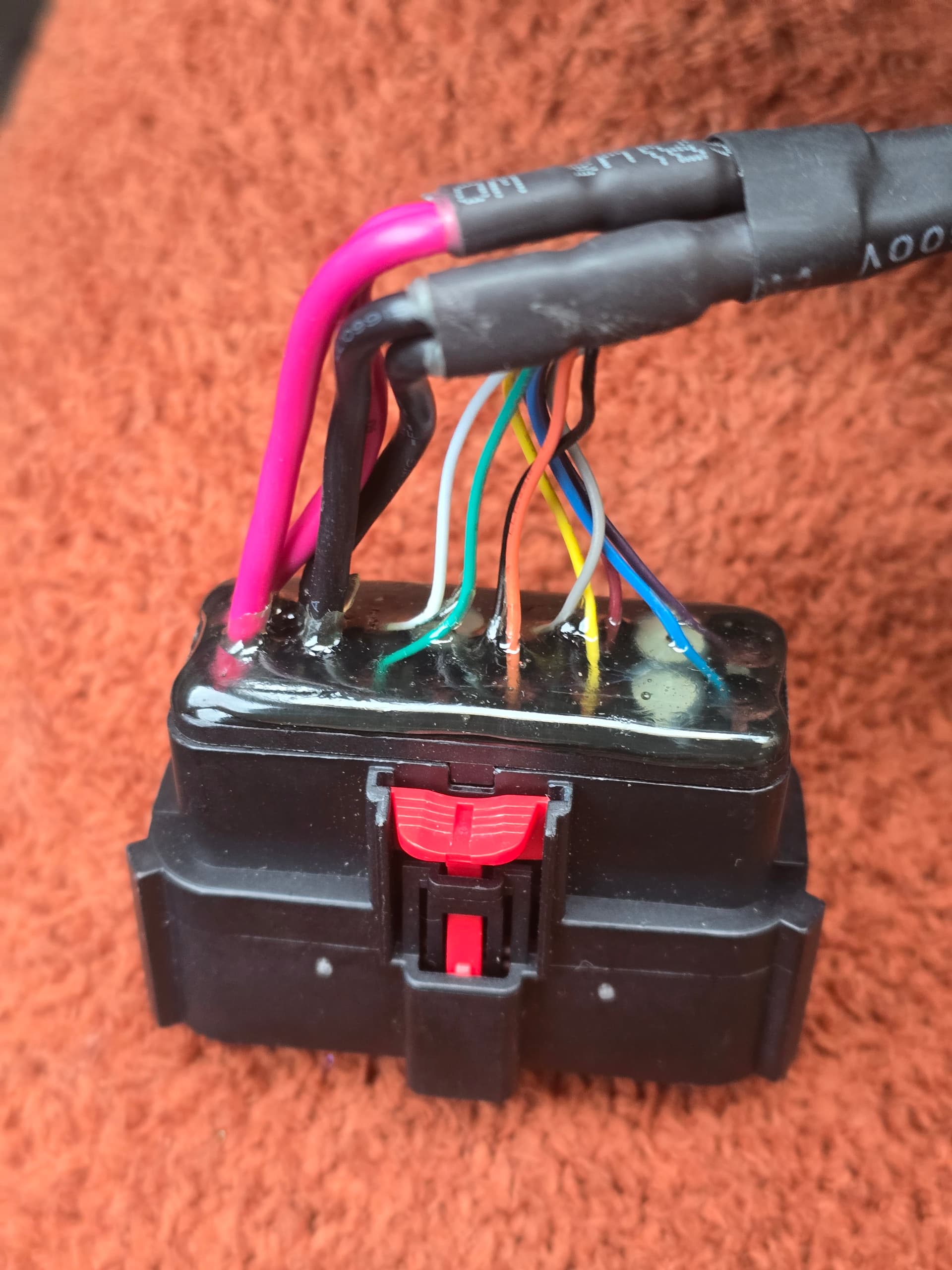
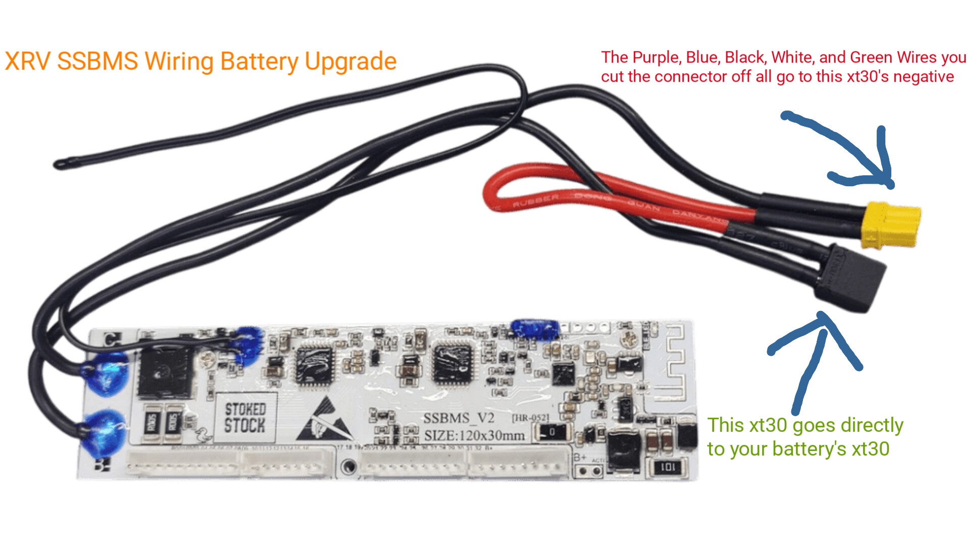
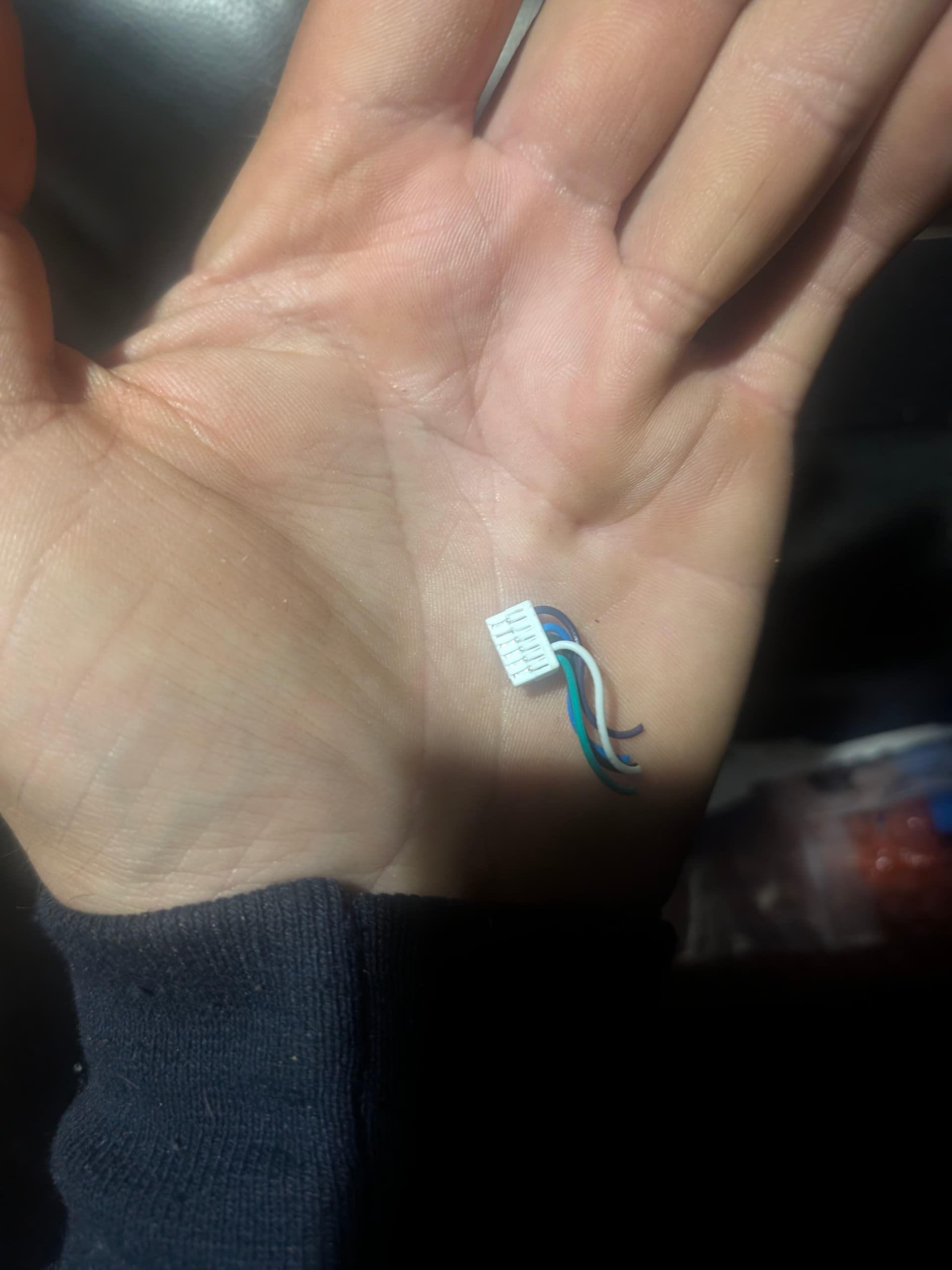
I will also help out now that I have done it, if installing a stoked stock bms on an XRV and keeping the factory harness as is and are trying to figure out the charge wiring, (Note: No need to open controller side of board at all) you just have to cut off the BMS communication plug that FloatWheel repurposed all 5 wires as the negative for the charge port which is currently being used on your Floatwheel kit BMS in your battery box.(Connector has 5 wires as follows, purple, blue, black, white, and green) So cut that connector off, twist them all together and solder them all to an xt30 on the negative side leaving the positive side empty because the positive is already wired into the main battery lead up in the controller box. By using the negative lead from the charge port to the BMS and then to the battery, the BMS is able to control that negative lead and stop charging which is what we are after. Remember to put some heat shrink on the xt30 positive pin your not connecting anything to for safety. Then connect the battery side of the BMS to the battery, usually with xt30, then connect charge port side of the BMS’s xt30 to the new cable you just soldered those 5 wires to the negative on the xt30 and your done. I didn’t take a picture when I did mine so here is some basic MS Paint drawings lol hope it helps someone!