Tools needed
- Allen Key: One for your hub bolts/inner hub bolts, 4mm for motor plate bolts.
- Soldering Iron, Leaded Solder
- Small zip-tie
- Tweezers
- Very thin heat shrink (1mm diameter recommended)
- Small Flat head screwdriver/bit
- Hammer
- Flush cutters
- JBWeld or Heat-resistant Super Glue
Estimated time: 1-3 hours, depending on skill level
Replacement hall sensors are the SS41F, they can be found on Digikey. This requires one to be familiar with disassembling a motor. Linked is a video that should help you get your stator out of your motor. It’s not difficult, but requires some body weight to separate the stator from the hub.
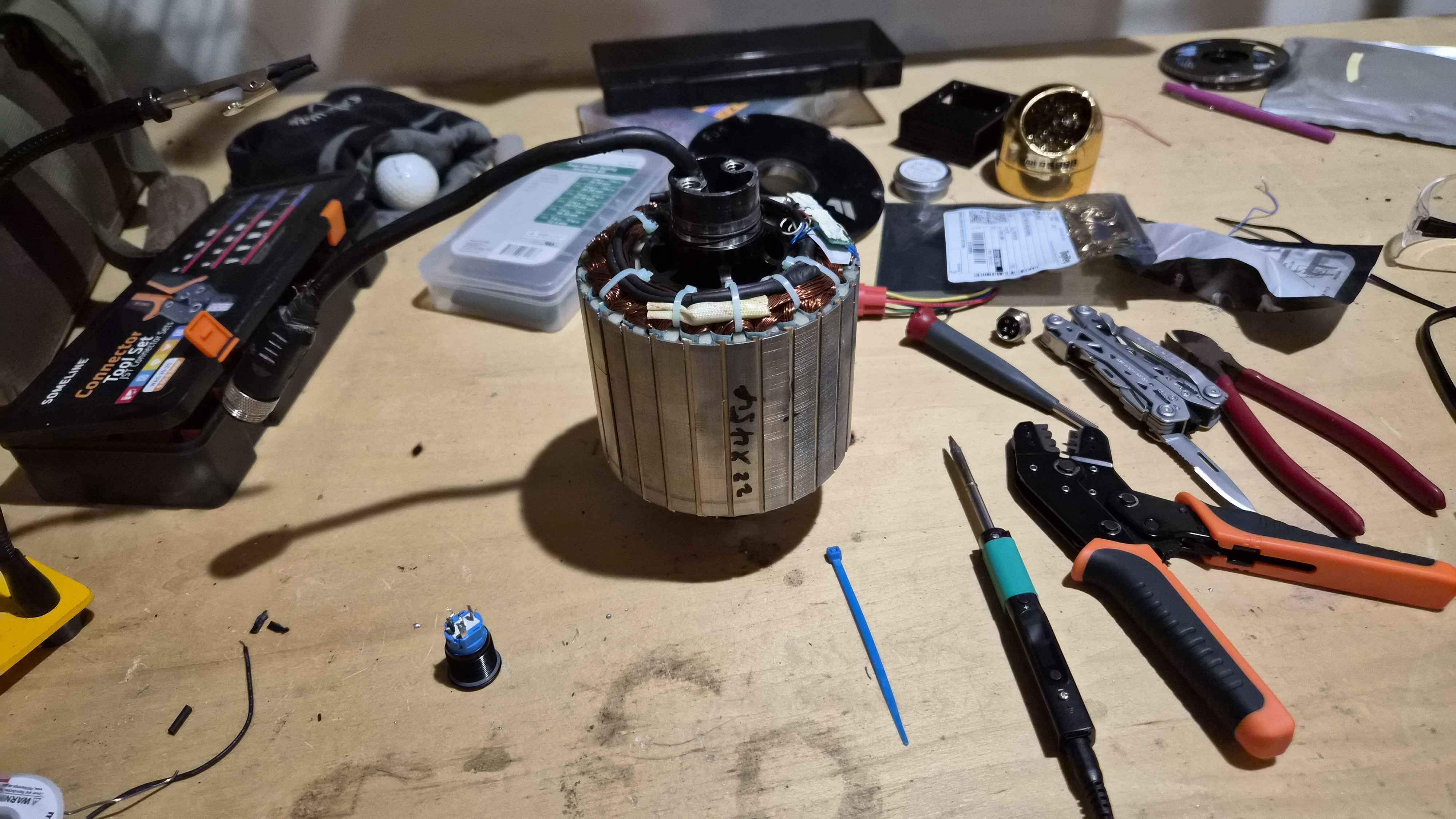
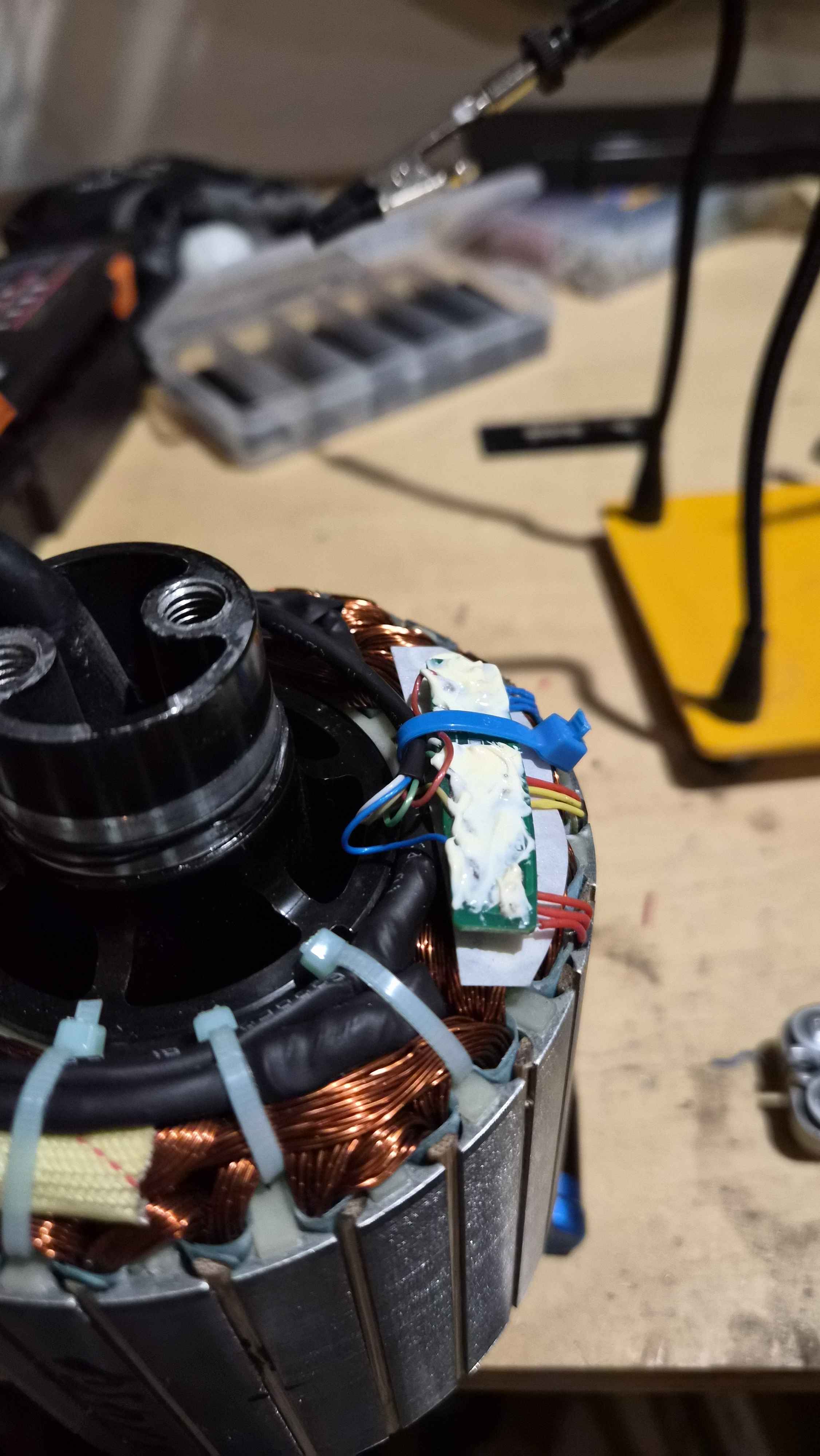
Once your stator is pulled out, it should look like this:
The hall PCB is held on with a ziptie, which can be cut off. The hall PCB is covered in epoxy, which you should do your absolute best not to disturb.
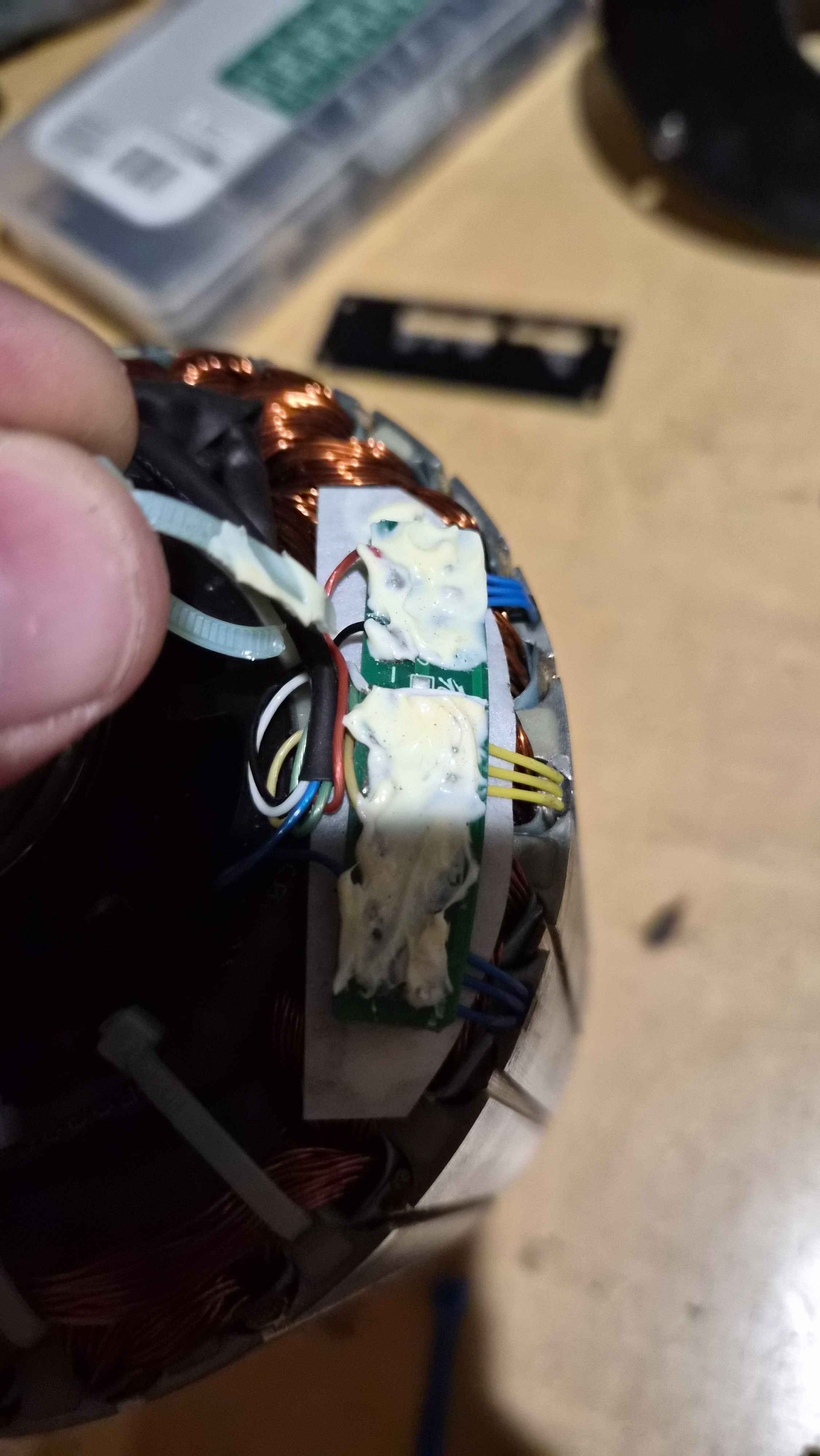
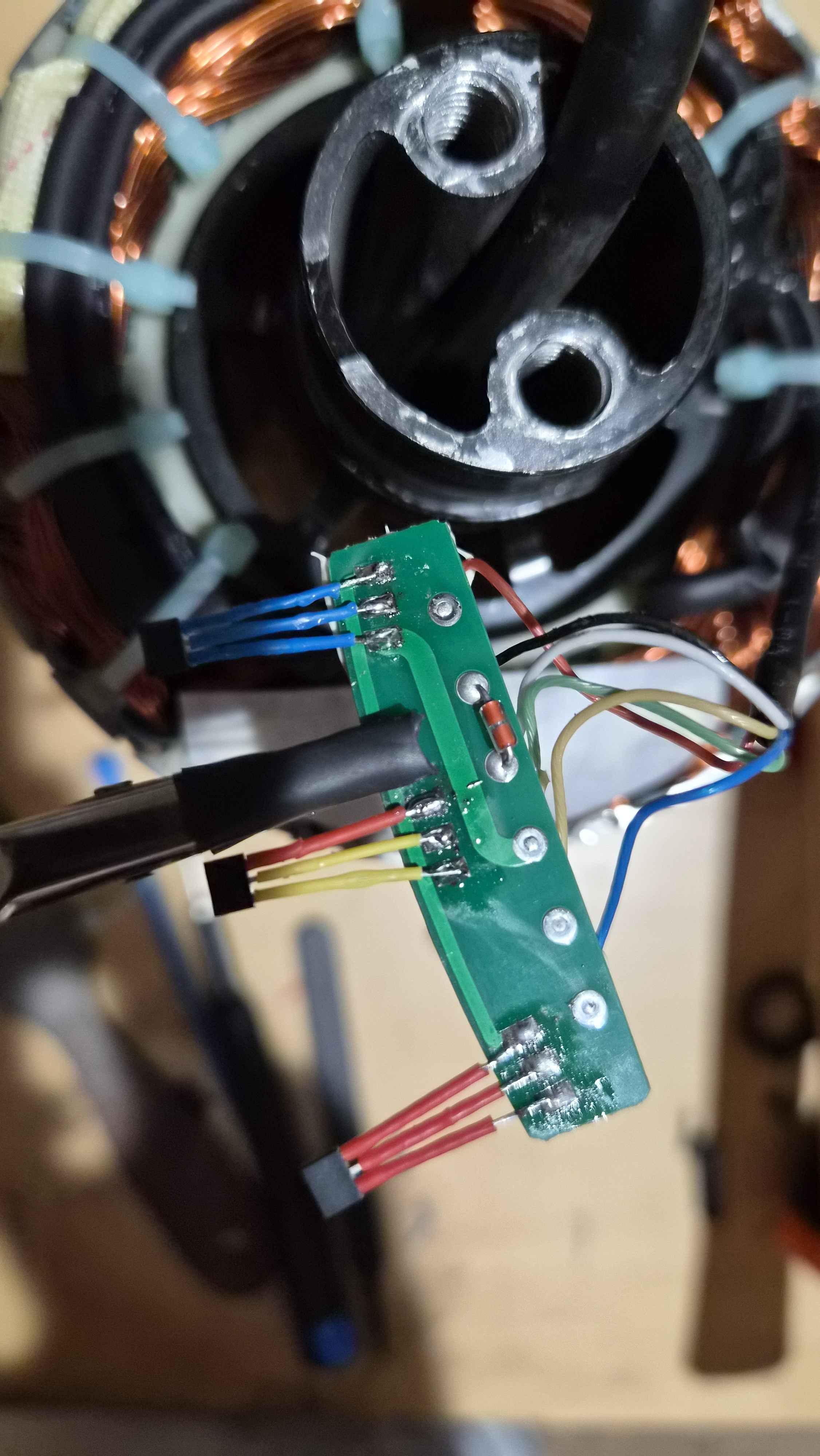
Carefully lift the PCB up, where you expose the solder pads in the direction of the axle itself. Do not force the PCB if you feel any resistance while moving it, and do not yank or tug on any cable plugged into the PCB.
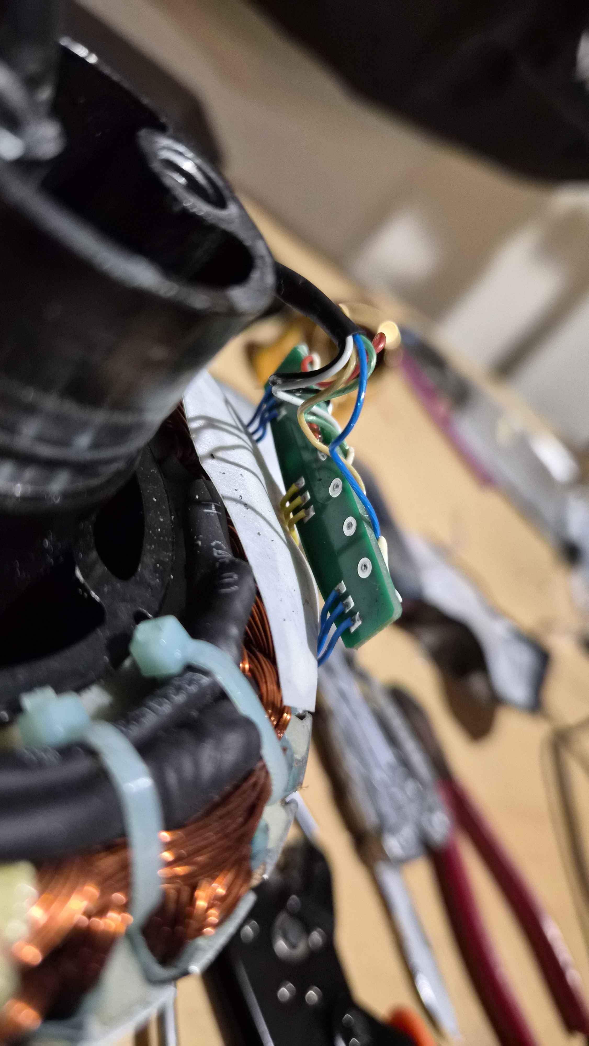
Carefully heat up each pad of the hall sensor leads, and use tweezers to carefully pull the lead away from the pad once the solder has melted.
Do one at a time until all wires are desoldered the and the PCB is no longer constrained by the hall sensors.
The hall sensors are held in with epoxy, and cannot be removed without some minor “persuasion”. It is recommended to use a small flat head and a hammer to chisel away at the hall sensor. You should aim directly for the hall sensor to break it. Use minor effort when hammering with the flat head blade parallel to the motor plates, as there is a good chance you many cause the plates to separate if your bit goes in between the layers.
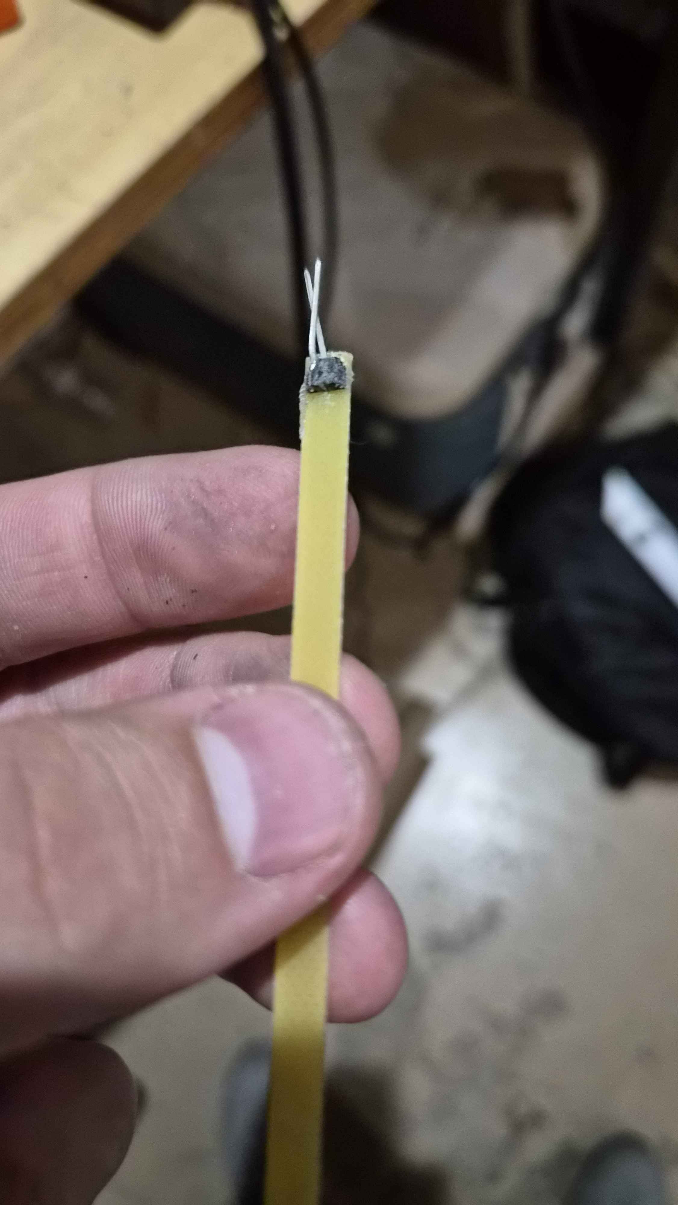
For the center hall sensor, you may slide the yellow slip it is attached to up and out of the stator. You can use a generous amount of heat (I used 360C at low air speed from a hot air gun) to melt away the glue, and tweezers to remove the sensor. Alternatively, you may clip off the hall sensor with flush cutters, and then file down what remains of the hall sensor.
When installing new hall sensors, it is recommended to have Soldering Helping Hands to help hold the PCB while soldering. You may either install the hall sensors into the stator first, or solder them to the PCB first then install them. Before soldering, you should apply heat shrink over the leads, leaving at least four to five millimeters of exposed wire to solder.
Either way, the flat side with no chamfers should face the stator itself, with the chamfered side facing outwards. Either apply a small dab of heat-resistant super glue or JBWeld to the flat side of the sensor, and slide it in. It is reccomended to check their fitment in the stator before trying this with glue. If it is a tight fit, you may need to sand/chisel away any remaining pieces of dried glue/old sensor.
Once installed, you should fold the PCB back down with the epoxy side facing up, and zip-tie the PCB back into the stator.
You may now reassemble your motor.