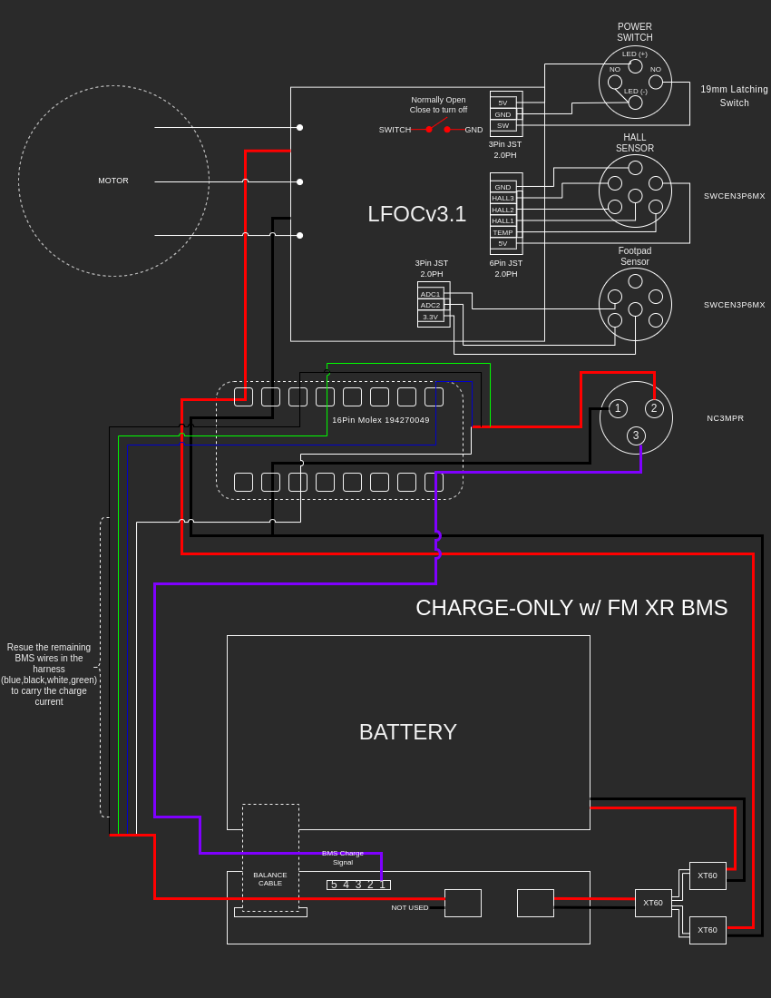
Charge-Only w/ Stock Harness
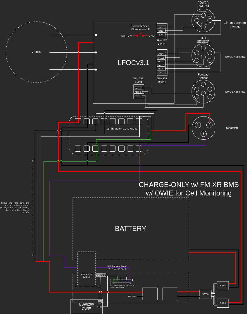
Charge-Only w/ Stock Harness + OWIE
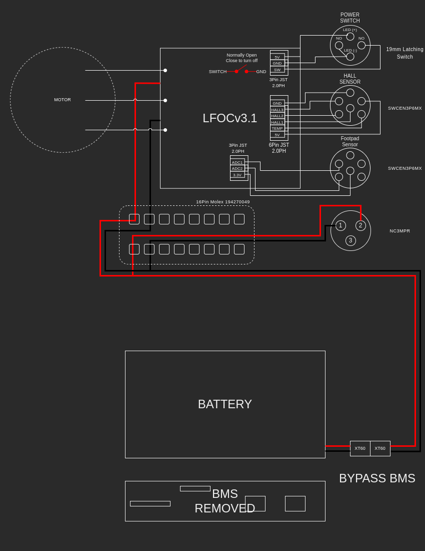
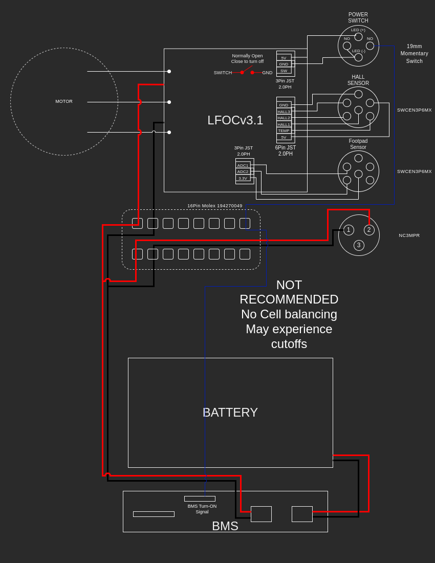
Bypass
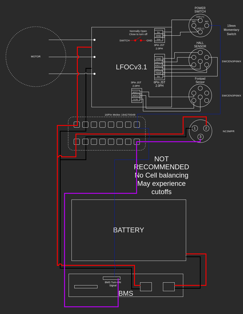
NOT recommended
Sharing for those interested
Charge-Only w/ Stock Harness
Charge-Only w/ Stock Harness + OWIE
Bypass
NOT recommended
Sharing for those interested
Thank you! This is helpful.
In this most recent diagram it shows the purple wire to pin 5, but on your first diagram it is shown on pin 1. The OWIE wiring guide also shows pin 1. Is this a mistake or is there something different about using pin 1 vs. 5?
Thanks for posting these! Helpful indeed. Can you tell me why the BMS doesn’t balance when using the “not recommended” momentary switch option?
Thanks. The purple wire is actually Pin 1 on the JST. Pin 1 is marked by a dot on the board and a notch/triangle on the stock connector. I’m not able to delete/modify the original post for some reason. Diagrams updated above.
If you short the blue wire- the BMS will turn on. That’s the BMS “switch” - and nothing else. The purple wire however signals to the BMS that a charge current is present so that it will balance.
Did I understand the diagram correctly: I need to cut the JST connector off, split the purple wire off and solder white, black x2, and green cables all together, basically treating the 4 cables as 1 thicker gauge cable, then solder that onto a male XT60 connector, and connect that to the female XT60 on the BMS?
So if I wanted to maintain compatibility with the stock FM controller, but also allow for cell balancing, could I connect the purple wire as well as the blue?
Like this:
@Icehoanng - Yes pretty much - but the colors should be black, green, white, and blue from the JST. You can keep the purple wire on the JST and plug it in. Then combine the black, green, white and blue wires to carry the charge current to the XT60 on the BMS. On the controller side those wires should be soldered together and connected to the XLR Pin 2. That’s only if you want to use the stock harness, you can always run your own thicker gauge wire straight from the XLR to the XT60 on the BMS and not mess with any of that.
Sure - i think that will work.
I personally was experiencing early cutoffs with the BMS-driven circuit so bypassed the BMS during riding and opted for charge-only.
Great, thanks for your input!
When did you experience cutoffs with the FM BMS? I ran the “not recommended” config for months before I upgraded my battery and I never had any issues.
Just did this installation and found one more minor mistake. On the BMS the 5V power supply pin for the OWIE chip was on the opposite side of the ground pin. The ground pin was correct.
I don’t me to pick on your work. I just really like this diagram. Very well done.
Thanks @izzy. I will update the diagram.
I am curious if you could add a owie-gum stick to your modified “NOT RECOMMENDED” configuration for cell monitoring?
That’s something that I would love to do eventually, but I haven’t gotten around to it yet.
Just some clarification on these diagrams, it seems that every time I come back to work on my VESC I have more questions about these. Due to the polarity of the XT60 connectors being “reversed” is the diagram drawn that the red wires match the color of those in the XR? Or is it just referencing the polarity of the wires? I am leaning more towards the latter but would rather not blow anything up after finishing my VESC.
The XT60 is reversed on the FM batteries and harness but red wire is still positive (+) and black wire is still (-). Keep red to red and black to black and you’re safe.