I will be keeping this thread up to date to provide the latest version of IzzFloat package. Izzfloat package is a modified version of Float package. It has features I designed myself primarily to improve trail riding capability.
Coming Soon: (if i can get it to work)
- Traction control
- Improvements to turn boost
Change Log:
Version 1.0.0.4
- Adds Angle P Scaling to the PID loop.
- To enable Angle P scaling, add Angle P, which must end in 0 or 5, to the desired angle where max Angle P should be applied (i.e. 15.5 applies 15 kp at 0.5 pitch angle. 21.5 applies 20 at 1.5).
- To disable Angle P scaling, Angle P should end in 0 or 5 (i.e. 15 20 25 etc).
- Updated turn boost. Brake boost has a 750 erpm low cut off so it does not act when coming to a full stop.
Version 1.0.0.3
-
Adds a secondary sticky tilt value. Hard coded to 6.0.
-
Engage secondary value by flicking throttle in direction of primary sticky value when engaged.
-
Sitcky tilt is persistant after disengaging the board to make restarting on high grades easier.
-
Turn on sticky tilt by adding a decimal to the end of max tilt value (i.e. 10.1 as opposed to 10.0)
Version 1.0.0.2
- Modified turn boost math to apply more consistently in low speed braking situations.
Version 1.0.0.1
- Updated to v1.0 FLOAT package
- Migrated turn boost, sticky tilt and surge behaviors
- TURN TILT ENTRIES NO LONGER EFFECT SURGE. Hard-coded all surge user entries to my perferred values for safety and simplicity.
- Start Angle Speed = 50 degrees/s
- Start Differential = 3 degrees
- Current Margin = 1.3
- Changed surge minimum angle to initialize to Start Differential to smooth out transition from braking to surge.
Version 0.9.1.1
- Replaces traditional pitch booster with roll based booster, Turn Boost
Version 0.9.1.0
- Adds surge behavior with differential pitch trigger
Version 0.9.0.1
- Adds sticky tilt input with hardcoded value of 3.0
ANGLE P SCALING
I have found that the ride feels much better with a reduced Angle P (kp) value when the board is close to the setpoint. This provides the advantages of having a low Angle P, while still giving the current you need at higher pitch angles.
This reduces freewheel spin during drops and bonks. It gives the board a suspension like effect when going over objects. Turn boost works much better on trails with this change. It allows for a higher maximum Angle P. Overall ride feel is greatly improved.
How Does it Work?
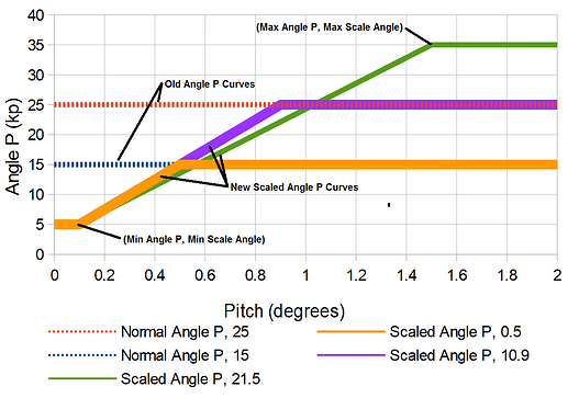
Angle P Scaling uses the pitch angle to determine how much Angle P to give you. It is currently coded to provide 5 Angle P from 0 to 0.1 degrees. From there it will ramp the Angle P up linearly to Max Angle P at angle, Max Scale Angle, as shown in the figure below.
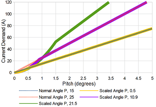
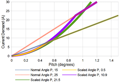
This creates a current demand curve that will look something like this.
Because we are using the pitch angle to determine the Angle P this can have negative side effects, primarily board vibration. I have applied a secondary Kalman filter to eliminate that. If you find vibration happening in certain situations please report it to me. If you are having trouble you can try halving your IMU frequency from 832hz for Little Focer 3.1 to 416hz. See the IMU calibration guide for more information.
Settings
Max Angle P – This defines the maximum value that the kp will scale to. User entry Angle P.
Max Scale Angle – This is the lowest angle that will give us Max Angle P. This will have a more significant impact to your ride than changing the Max Angle P, 0.1-0.2 degrees of change is noticeable. User entry Angle P.
Min Angle P - This defines the minimum value that the kp will scale to. 5, not a user entry.
Min Scale Angle – This is the highest angle that will give us Min Angle P. After this angle, kp will scale linearly from Min Angle P to Max Angle P. 0.1, not a user entry.
Setup
To avoid making new UI, which I will have to continuously update, I am making use of the Angle P input as two inputs. The first part of the input will be the Max Angle P which must end in a 5 or a 0, i.e. 15, 20, 25, etc. The second part will be your Max Scale Angle, i.e 1.5. If we want a Max Angle P of 20 and a Max Scale Angle of 1.5 we will enter 21.5 (20 + 1.5) into our Angle P entry.
If you would like to disengage Angle P Scaling only use a number ending in 0 or 5.
FYI, I have also rescaled to automatically add 15 to the Angle P value when Angle P Scaling is engaged. Higher values are preferred with Angle P Scaling. So an entry of 21.5 is actually maximum Angle P of 35 (20 + 15). If you are used to riding Angle P 25, Max Angle P of 20 with Angle P Scaling should feel pretty good.
Rate P should be set to 0.2 to 0.5. Higher values feel too stiff to me and tend to erase the scaling effect. Combining different Rate P’s with different Max Scale Angle’s can yield interesting effects.
Here are some settings you can try out:
| Lowest | Street | Trail | Highest | |
|---|---|---|---|---|
| Tight | 0.3 | 10.5 | 20.7 | 31 |
| Middle | 0.5 | 10.9 | 21.3 | 31.9 |
| Loose | 0.8 | 11.4 | 22 | 32.9 |
TURN BOOST
This was a very simple change to the float package. I took the booster and changed it to be based on roll instead of pitch. The result allows you to tune the board so that it accelerates into your turns. This works with the existing booster inputs.
Why is this important?
When you want to turn sharply, you have to lean to the inside of the turn. This puts your center of gravity on a smaller turn radius (the path your center of gravity takes) than the board, which will be taking a larger turn radius. A smaller turn radius is a shorter path to complete the turn so the board has to go faster (or your body slower) in order to make the turn. The harder the turn is, the larger the difference between the path length of the board vs. your center of gravity.
Normally, we accelerate the board by pushing the nose down but in some scenarios this will cause the nose to contact the ground, particularly at high roll angles. Turn boost compensates by using the roll so we don’t have to nose down. This allows for a smoother, natural-feeling turn that can also be programmed to be quite “boosty”.
Settings
The settings work very much like the traditional booster but with roll (side to side motion of the board) as the trigger. The boost will start at boost angle and increase at rate: boost current, divided by boost ramp. The boost current is now a percentage that is multiplied by the PID current demand so that turn boost does not override our PID control loop.
For acceleration boost, having a large boost ramp with settings, like boost angle 5 and boost ramp 10, will give a very rounded carvey feel. It will be loose but the extra current is there when you are really deep into a carve. On the other hand, a small ramp, like boost angle 5 and ramp 1, will give a very tight “race-like” feel. It keeps your carve very narrow and controlled. Both these settings will provide excellent low speed maneuverability.
For braking, the boost acts a little differently. Because we want the board to accelerate around our turns, the brake boost acts opposite to the PID control loop to release the braking force. I have not been able to experiment with this as much as I would like because I live somewhere pretty flat, but the results so far have been good. It feels much more like a snowboard in the way it accelerates through the apex of the carve. Doing a snowboard-like sideways stop also feels good. The settings I have used for braking are boost angle 5, boost ramp 3, boost current 60.
Please be careful using high boost current values for braking. As I mentioned, it is percent based and 100% could remove all braking force. In my tests this has not been a problem yet.
SURGE
What is Surge?
Surge is when the board gives you maximum motor output. The trigger to activate surge is a quick nose dip (pitch differential). When surge is activated it will push the nose up as quickly as possible and will end from a variety of conditions including pitch, current demand, and traction control.
Surge Parameter Descriptions
Start Angle Speed (degrees/s)
This is the nose dip speed that can initiate surge. Lower speeds allow for surge to be initiated more easily. Higher values will require more effort to surge. This has a relatively low level of importance because the actual angle speed can vary quite a bit. We just need a reasonable boundary between normal nose dipping and nose dipping that causes surge. Default 50. Not a user entry.
Differential Limit (degrees)
This is the cumulative pitch required at the Start Angle Speed to initiate surge. This has a high level of importance because it will affect the sensitivity of the surge trigger. A small value can cause nuisance trips in bumpy conditions or initiate the surge too early. A large value will make it hard to surge. Default 3.0. Not a user entry.
Current Margin (-)
During surge the PID loop is still running and reports the current demand but this demand is not used. As the pitch returns to the setpoint, this current demand naturally reduces. If it is reduced to less than the surge current (maximum continuous current), the surge cycle ends and PID control can resume.
In addition, the Current Margin is applied to the surge current when compared to the PID demand so that we can end surge later. For example, the surge current is 55A, our pitch is travelling back to setpoint and now demanding 30A. Our surge margin is 1.5. If 30A < 55A / 1.5, we will leave surge. This is true so we will leave surge. In this example, a surge margin of 1.0 would leave surge earlier and at a higher pitch angle and higher current demand.
You will also notice that since this is tied to the PID loop your PID tuning will affect how soon surge ends. Low proportional factors of 10 will leave surge earlier (at higher pitch angles) and may require higher Current Margin to get the surge cycle you want. On the other hand, high proportional factors like 25 will leave surge at much lower pitch angles and have a higher chance of overshooting at high Current Margin.
The minimum recommended value for current margin is 1. Lower values will leave surge early and less than 1 could have negative consequences. High values will leave surge later. This provides more power but could “over-surge” which causes the pitch to overshoot the setpoint. Once surge ends the board can abruptly brake, which causes the board to feel stiff. This has a high level of importance since it is the main condition that ends surge. Default 1.3. Not a user entry.
Surge Period (s)
The minimum amount of time between each surge start. Should be greater than surge cycle. The closer the period is to the surge cycle the greater the risk of instability and loss of control. This has a high level of importance since this will provide a delay between surge cycles. Default 0.75. Not a user entry.
Surge Cycle (s)
The maximum amount of time that surge can be engaged. Lower values can give less power. Higher values can cause issues in extreme situations. This has a low level of importance since one of the fault conditions will usually end the surge cycle early. Default .30. Not a user entry.
Minimum Angle (degrees)
The minimum nose down, pitch angle from setpoint in the direction of travel, required to engage and continue surge. Higher values can end surge prematurely. This has a medium level of importance. This will not usually trip but it is important that we are asking for acceleration when we surge. Default 0.05. Not a user entry.
STICKY INPUT TILT
This feature allows you to use your remote to set two persistent nose up and nose down angles. To reset the angle to zero you just push your throttle in the opposite direction for a moment.
Description of Behavior
The default sticky nose up and nose down angle is currently hard coded to 3 degrees. It engages as the throttle is traveling back to the center position. If it passes through the sticky value, it will stay at that value.
For example, you nose up 10 degrees and release the throttle back to center. The nose will stick to 3 degrees up even as the throttle rests at the center position. If you push the throttle nose up again, the angle will not engage further until 3+ degrees.
If you then push the throttle nose down, you only need to do so for a split second to reset the board angle back to zero from the nose up sticky value. The same is true if you are nose down. Push the throttle nose up to reset. It only needs to be for an instant so you can just flick the throttle.
With version 1.0.0.3 there is now a second sticky value that is higher than the first. This is hard-coded to 6.0 degrees. When sticky tilt is engaged at the first value you can flick the throttle in the direction of the sticky tilt value to move it to the second value and visa versa. Moving the throttle in the opposite direction will still end sticky tilt no matter which value you are at.
If the setpoint reaches max while pushing the throttle in the direction of sticky tilt value, it will not switch sticky tilt values. This means that if you are going downhill at sticky value 6.0, and you want to throttle to max (i.e. 10) for a quick drop, you will then return to 6.0 when you throttle down and not switch to 3.0.
With version 1.0.0.3 sticky tilt is now persistent when you disengage and re-engage the board. I added this feature because it can be difficult to start back up after falling on a steep grade. Input tilt will not be persistent for any values other than the sticky tilt values. Input tilt will not be persistent if your remote turns off or loses communication.
How to enable
With version 1.0.0.3 sticky tilt can be enabled/disabled. To avoid adding more UI, sticky tilt is enabled via the maximum input tilt angle. To do this you just need to include a decimal other than 0 in your maximum tilt value. For example, use 10.1 instead of 10.0.
Why
This is for trail riding specifically. My typical trail rides are not as dynamic as a pump track or skate park, but I live somewhere pretty mountainous. 4,000ft of elevation change is not unusual for my rides so I spend a good amount of time on steep uphill or downhill grades. I like riding those at 5-6 degrees nose up/down, but holding a specific angle is very difficult especially in choppy terrain.
ATR has been great for providing the angle I want but I find that automatic setpoint changes have undesirable side effects. Primarily, it removes the sense of board level that my body determines through the position of my knees and hips. This sense allows me to predict how the board will act, but if the setpoint is constantly changing my sense is blurred.
Sticky tilt allows me to predetermine the setpoint I need for the terrain. My body only needs a second to register this new setpoint and have a full sense of where the board level is. Now with 5 distinct setpoints (-max, -6, -3, 0, 3, 6, max), I can comfortably handle any terrain without automatic setpoint changes.


