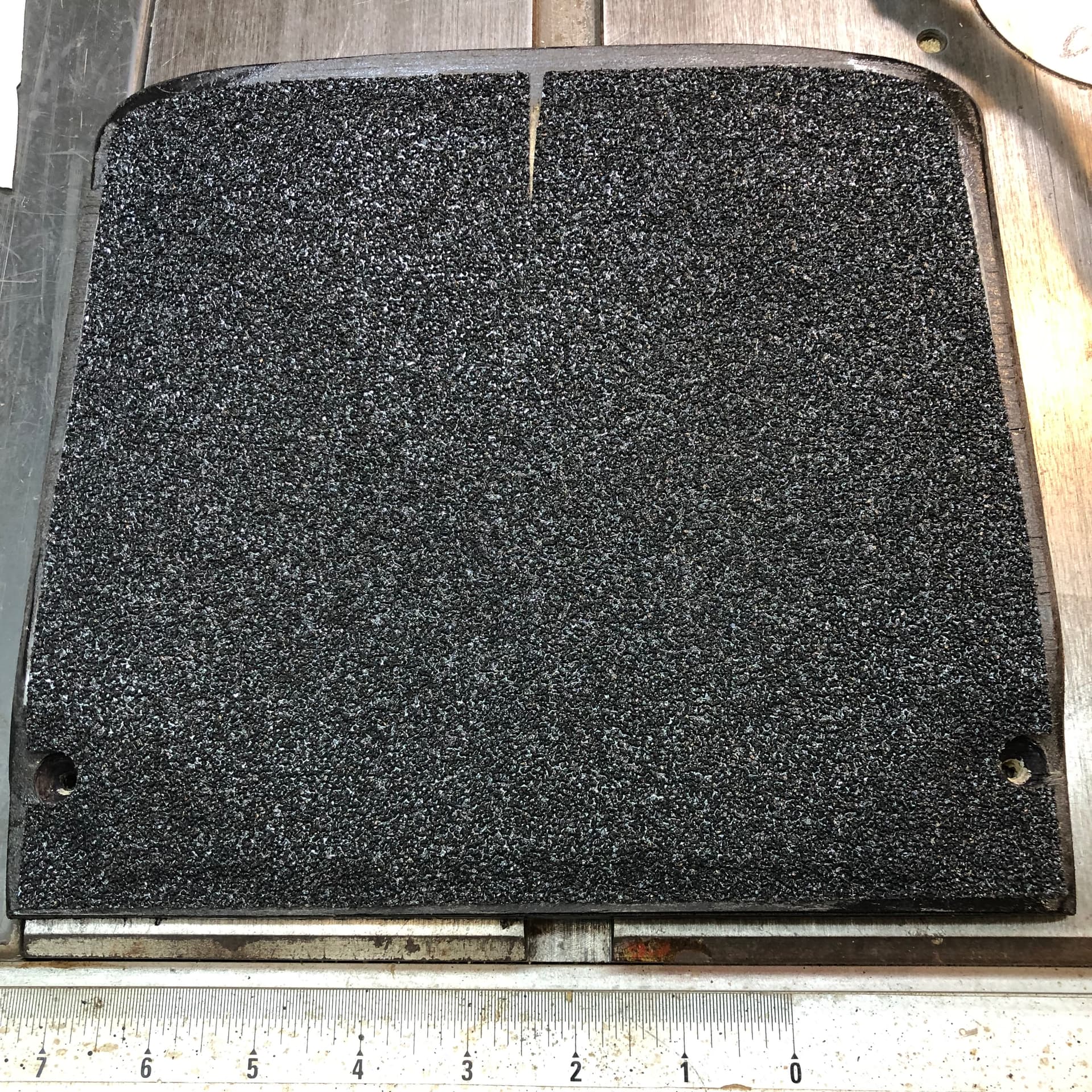
This guide provides examples and instructions for creating and modifying custom front footpads for your Onewheel, focusing on support, durability, and cooling.
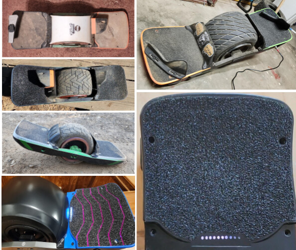
Example of custom front footpads.
GT vs. XR Footpad Comparison
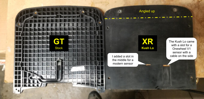
Comparison of GT and XR footpads.
Terminology
For the purpose of front footpads, XR, Plus, and VEXR (VESC with XR-compatible rails) are interchangeable. Even an OG V1 Onewheel has the same rails as an XR, so it can take XR-compatible footpads if you also swap out the bumpers.
Similarly, GT, GT-S, GTV (VESC with GT-compatible rails), and XR Classic (looks like an XR, but uses GT-compatible parts) are interchangeable.
Why Add Footpad Plates?
The reasons for adding a plate under your front footpad include support, durability, and cooling. Most stock FM footpads are hard wood or plastic. Most aftermarket footpads are soft rubber or urethane, providing little support and putting the controller box lid at risk of being damaged from the weight of your front foot.
XR/Plus footpads are symmetrical, but the controller box lid only supports the front two-thirds of the footpad. A metal plate under the front footpad provides additional support, keeps out dirt, and if your controller box has a metal lid with the controller mounted underneath, an additional metal plate on top will help cool the controller.
GT front and rear footpads are asymmetrical, and most aftermarket GT footpads are designed to go on the rear of the board. The GT battery box is taller than the controller box, and a plate fills the gap when a rear pad is used in the front.
Thor controller boxes from Fungineers extend further back toward the tire than the stock XR or Flowglider boxes, but they have thin plastic lids. If you use a split pack in the Thor box, then the split pack brackets will support the lid. Otherwise, it might be a good idea to use a support plate.
Materials List
Here’s a list of materials needed for your custom footpad project:
-
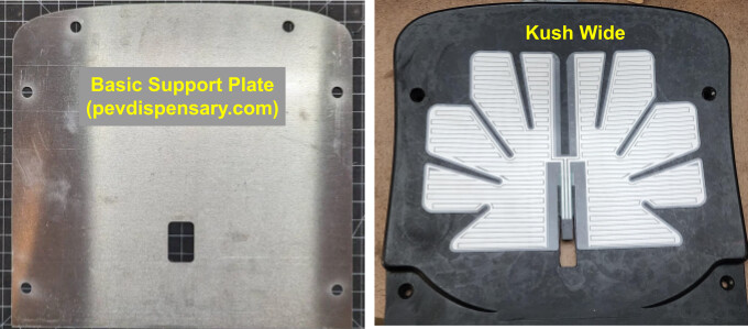
Aftermarket Rear Footpad: (e.g., GT Kush Wide)
Aftermarket rear footpad example. -
Footpad Plate (DIY or premade):
- GT Platform: Cut to fit battery box depression inside footpad, with sensor and LED bar cutouts.
- XR: Cut the footprint of the entire footpad or buy a premade footpad plate. PEV Dispensary and others make aluminum XR footpad plates. I’m unaware of anyone who sells premade GT footpad plates, so you’ll need the additional supplies below.
-
Sensor: Gently removed from stock GT footpad, or aftermarket (e.g., Stoked Stock V3 or V4).
-
Grip Tape: Of choice (perforated recommended).
-
Clear Silicone Sealant (optional)
-
Heat Gun or Blow Dryer
-
Hot Glue Gun, Hot Glue
-
Electrical Tape
-
180 Grit Sandpaper
-
Isopropyl Rubbing Alcohol, 91-99%
-
Wood Strips: Such as paint mixing sticks, 1/8" thick.
Example of wood strips. -
Urethane Roller (optional)
Urethane roller example.

Additional Supplies to Make Your Own Support Plate
- 1/16” thick 6061 T6 aluminum plate (4-pack on Amazon)
- Jigsaw with metal-specific jigsaw blade (fine-tooth)
- Drill with a drill bit large enough to fit the jigsaw blade through the hole
- Fine metal file or sandpaper
Additional Supplies to Make Your Own XR or GT/Pint Pigtail
- Plug:
- Plus, +XR hall & footpad (Switchcraft EN3C6FX on Digikey) or…
- GT/GT-S/XRC/Pint/Pint X (Amphenol AU-05BFFA-LL7001 on Digikey)
- Sensor Plug: 3-pin (30 Sets Servo Plug Kit on Amazon)
- Sensor Pigtail Wire: (22 Gauge 3 Conductor, 25FT on Amazon)
GT Support Plate Fabrication
Skip the plate fabrication steps if you purchased a support plate instead of making your own.
First, create a template by tracing the recessed area inside the footpad as shown below left, leaving about a 1/16” border all around (it should have some room to move and accommodate the footpad flexing when screwed in place). I used cardboard from a cereal box for the template.
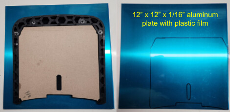
Creating a template for the GT support plate.
Next, transfer the template to the aluminum plate.
Drill a 3/8" hole to get the jigsaw blade into the cable slot.
Cut along the lines, then file or sand down the burrs.
Some variations of the GT footpad plate are shown below. Use the stock footpad as a guide for where to put the sensor cable hole and light bar notch.
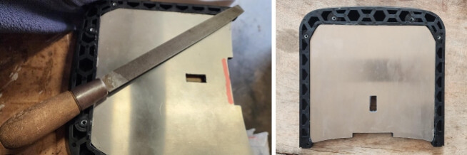
GT footpad plate variations (example 1).

GT footpad plate variations (example 2).
GT Footpad Modification
You’ll also need to cut the footpad itself. I like to first create the plate, then use the plate as a guide for using a utility knife to cut the light bar slot, and a slit for the sensor cable.
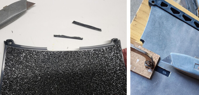
Cutting the GT footpad for the light bar and sensor cable.
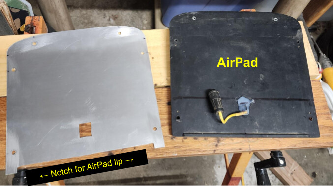
XR Support Plate Fabrication
I’ve done a few variations of the XR footpad plate. They all start by simply tracing the footpad itself onto the metal plate with a Sharpie, marking the screw holes as well. You only need to cut a slot for the sensor cables, and many XR footpads already come with the slot in place. You’ll notice that XR footpads have a slight angle to them. I have yet to see a commercial plate that comes bent for this angle. I bend all my plates to follow the line of the footpad+bumper, which looks cleaner and keeps dirt out of the gap. See below for examples.
XR footpad plate fabrication (example 1).
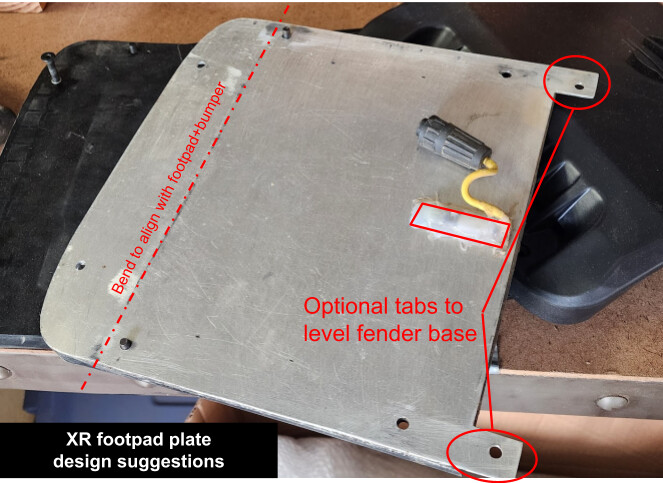
XR footpad plate fabrication (example 2).

XR footpad plate fabrication (example 3).

XR footpad plate fabrication (example 4).
Footpad Support Plate for Fungineers Thor Box
The Fungineers Thor box requires a different support plate design as shown here.
Thor box support plate design.
A support plate may not be needed when using a split pack battery in the Thor controller box if you are using a rigid footpad or your split pack brackets provide adequate support to the controller box lid.
XR or GT/Pint Sensor Pigtail Wiring
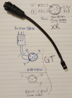
Sensor pigtail wiring diagram.
See images.
Key: R = Red, K = Black, Y = Yellow
Plus and +XR use the Switchcraft EN3C6FX plug
GT/GT-S/Pint/Pint X use the Amphenol AU-05BFFA-LL7001 plug
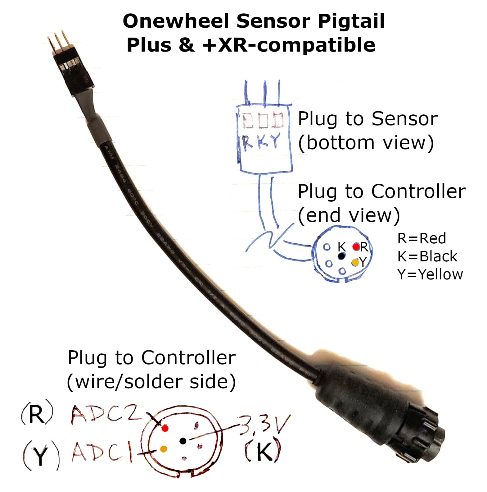
Onewheel XR sensor pigtail.
Assembly Instructions
-
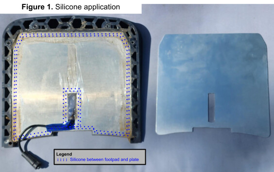
Seal Plate to Footpad (GT, optional): Apply a bead of silicone around the perimeter of the footpad, between the plate and the footpad. Also, add a very thin layer of silicone to the trailing edge of the plate and around the sensor cable slot (see dotted lines below). The silicone should be in a thin, wide layer, so it doesn’t affect the thickness of the footpad+plate assembly.
Sealing the plate to the footpad. -
Cure: Flip the assembly over, then place some supports under the plate (thin strips of wood, such as paint mixing sticks work well), then add some weight on top of the footpad. Allow to cure overnight, so the footpad and plate become one piece.
Curing the footpad and plate assembly. -
Cut Sensor Cable Hole: After the silicone between the plate and footpad is dry, determine where you want your sensor to go (minimum of 1" in front of LED bar) then cut a rectangular hole through the footpad with a utility knife for the sensor cable (see below).
-
Prepare Footpad: It’s recommended that you roughen the top of the footpad with rough sandpaper (180 grit) to make the sensor and grip tape stick better. Be sure to clean the footpad with 99% rubbing alcohol, then let dry.
-
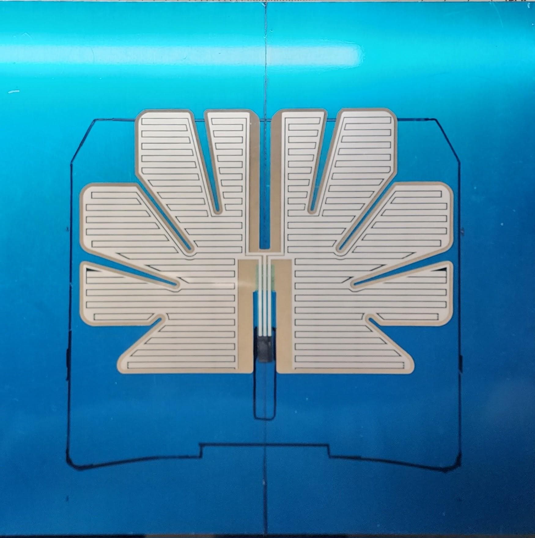
Prepare the Sensor:
- Stoked Stock V5: The V5 sensor is too big for the Kush Wide footpad, but it’s designed to be cuttable. Pre-fit the sensor and trim away sections as shown above, right.
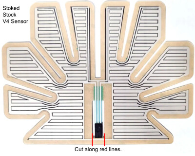
- Stoked Stock V3/V4: If you have a Stoked Stock V3 or V4 sensor, it must be modified to work with the heel/toe lift (dual zone), otherwise it will be in “posi” configuration where you have to take your entire foot off the footpad to deactivate the sensor. Modification is simple. If you want a standard dual-zone sensor, just cut out the “bridge” section below the connector ribbon as shown.
Modifying a Stoked Stock sensor.

A urethane roller is recommended for the next two steps.
-
Install the Sensor: Peel the backing off the sensor from the middle out. Stick down the middle area by the cable, making sure it’s fully adhered with no trapped air bubbles, then peel the backing away as you work slowly out to the edges, similar to the grip tape below.
-
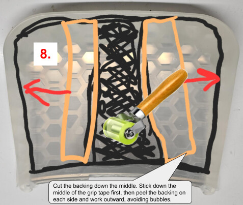
Apply Grip Tape: Peel the backing off the grip tape from the middle out. Stick down the middle area at the lowest point of the concave first, making sure it’s fully adhered with no trapped air bubbles, then peel the backing away as you work slowly out to the edges.
Applying grip tape. -
Connect the Pigtail to the Sensor: Use a heat gun or blow dryer to remove the hot glue holding the pigtail from your old sensor. Connect the pigtail to the new footpad assembly and plug it into your board to check that the left/right sensor zones correspond to the left/right LEDs. A stock Onewheel with the footpad light will indicate which sensor side is detected. If you don’t have a footpad light, both the Onewheel app and the VESC Tool will indicate which side of the footpad it senses. Flip the pigtail plug over if left/right appear reversed in the app.
Sealing beneath the footpad is optional. I don’t seal with silicone anymore because I take apart and clean my board underneath the footpads frequently.
That said, the purpose of sealing up the footpad with silicone is to prevent dirt and water from collecting between the top of the controller and the bottom of the footpad. Hot glue and silicone are not permanent and can be easily removed. The assembled footpad below left in Figure 2 got some more silicone before being reinstalled with clamps and allowed to cure overnight. These days, I just use hot glue on the controller pigtail.
-
Hot Glue:
- Fill the sensor cable hole with hot glue.
- (Optional) Fill the ends of the channels on each side of the controller with hot glue.
Applying hot glue. -
Tape the Sensor Pigtail (GT only): Tape down the sensor pigtail so it slots into the channel in the controller.
-
Seal Under the Footpad (optional): Apply a thin, contiguous bead of silicone to the controller box and rails as shown in Figure 2.
-
Final Assembly: Assemble the bumper, footpad, and fender/fender delete.
- (Optional) If you added silicone, then gently clamp each side of the footpad down to the rails about halfway between the front and rear bolts to seal it to the rails, then let cure overnight.

Options
Status LEDs
GT(S), XRC, Pint LED Bar: It’s recommended that a stock FM footpad be used as a guide to cut the LED bar notch in the new footpad (see dotted lines above). A support plate can also be used as a guide for cutting the LED bar notch if you don’t have a stock footpad to use as a guide, but be careful not to cut away more material than necessary, since the support plate has greater clearance than a stock footpad.
XR VESC with status bar (e.g., Thor300/400): Ten separate holes (one above each LED) provide clearer status information than a slot. I created a jig that’s aligned to the status LEDs across the footpad via the inner footpad/rail bolt holes (see below). Start with small holes (1/16” or 1.5mm) and work your way up to larger holes (3/16” or 5mm).
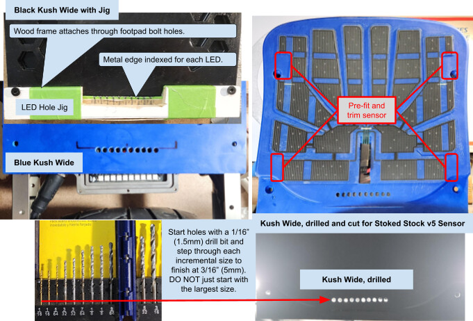
Jig for drilling status LED holes.
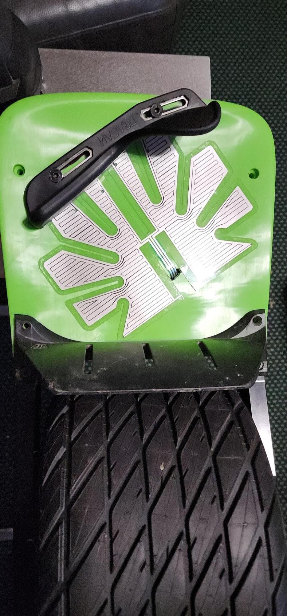
Foot Holds
I’ve used FlightFins, Overlander Lifters, and Dragan Hooks. The Dragan Hooks are definitely the cheapest option out there at around $70/pair, but they’re also the hardest to install because you need to either buy an expensive mounting plate or drill holes through your footpads like I did. If you want to use Dragan Hooks without the expensive mounting plates that also limit where you can install them, it’s easiest to line up the bolt holes before applying the sensor, then add grip tape and bolt them on knowing that they won’t interfere with the sensor. The Stoked Stock v5 sensor can be cut to disable regions where the footholds touch, and a v3 sensor may be small enough that you can work around it. I use a diagonal foot stance, so I stuck my sensor on diagonally with the left side under my heel and the right side under my toe as shown here on a Platypus footpad.
Diagonal sensor placement with foot holds.
Tips and Lessons Learned
- Some people say footpad plates are unnecessary. Unless you’re using a wood or hard plastic footpad that doesn’t flex, a footpad plate will make your build more structurally sound, among other benefits. Even an AirPad that has an internal metal frame will flex above the connector plug area between the controller box and the tire. The plate not only reinforces the controller box lid, but acts as an additional heat sink for boxes with metal lids to keep your controller from overheating. Aftermarket GT footpads don’t touch the top of the controller box without the plate filling the gap. Unsupported footpads collect a lot more dirt underneath them.
- When installing footpads, first put all the screws in loosely to make it easier to line everything up before you tighten it up.
- Most varieties of Loctite, including the common Loctite 242, destroy plastic if only a tiny bit comes in contact, but you can use Vibra-TITE VC-3 thread locker to keep screws from coming loose.
- I do not recommend footpad plates made out of steel. Steel is a poor heat conductor and is a lot heavier than aluminum.
- It may help to put the footpad in the freezer if the screw holes don’t line up with the rails.
- Don’t bother trying to put the sensor between the support plate and the footpad. I’ve tried it and it works great until it doesn’t, and your sensor gets stuck on and your board ghosts away from you.
Thanks
Thanks to the awesome PEV community for the constant stream of new ideas and inspiration! I do my best to give back to this community and hope you find this and my other build guides helpful. All of my guides are posted to pev.dev.
-Kevin Pedersen