There is a new feature I am working on that I think everyone will enjoy, but I don’t know the best way to implement it. I want to put it out there early because @surfdado and @NicoAleman are so good at UI and implementation, maybe ya’ll will have good ideas. Or maybe there is already a way to do this without changes that I haven’t seen.
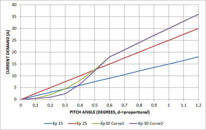
I have been calling this feature Angle P scaling and I discovered it by switching between VESC and my FM pint. I believe this is one of the factors that make the mission-like ride of the onewheel. It is essentially a reduction in Angle P close to the setpoint to provide a reduced reaction. Here are a plot I made for myself to understand the math with a couple curves I have been riding.
I typically trail ride with a Angle P (kp) of 25 shown in red. The lowest I will ride is kp 15 on the street shown in blue. This plot ignores the I and rate P factors for simplicity since they are time related.
The curves I have enjoyed riding are shown in green and purple. They have a minimum kp of 5 and a maximum kp of 30. They cross the 25 kp line at about 12 A which is a typical cruising current for me. This means I won’t need more angle for my typical velocity. Additionally I gain about 0.2 degrees more clearance at 30 A which is a typical high load.
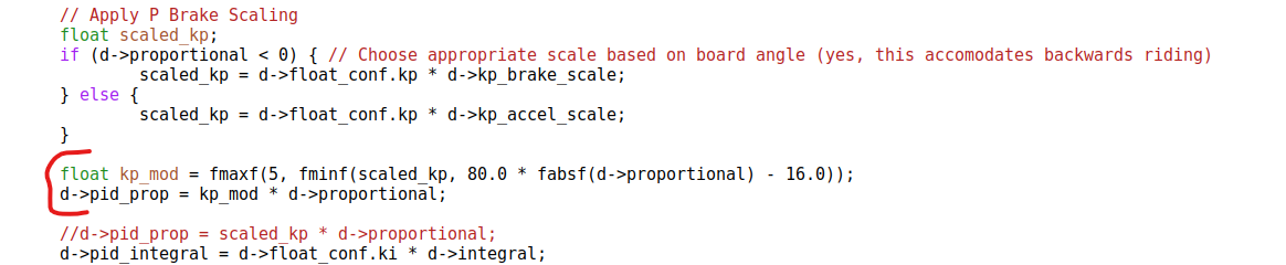
Here is my current implementation with (var1, var2) as (50, 0) for the green curve and (80, 16) for the purple curve:
It has a really nice floaty feel without being too loose. I think the I factor and rate P help control this.
It helps control free wheel spin during bonks and drops. If you keep the board around level the reaction is very mild. I have working traction control behavior now and it is much more effective with this change.
Similarly, it allows for smoother landings because of free wheel spin control.
It allows for higher Angle P values without making the board too sensitive at low pitch.
I feel less board reaction from bumps in the trail
Transition from braking to acceleration and visa versa has an interesting feel. Smoother in a way.
btw, I always kinda felt like the opposite was needed - to me the XR/Plus feel super stable in the center but then get softer as you push further, hence my attempts to stiffen the board in the center, e.g. when I used center-booster where boost only applied from 0-1 degree effectively increasing P for the first 1 degree
nevertheless, I like the simple yet non-linear curve that you can apply with your method…
how to explain this feature to the average rider? Good luck
So there is some vibration that i am sorting out. I did notice it but I thought it was related to turn boost so that it would not effect you. But after my trail ride this weekend I see that it is more likely related to Rate P.
I think the reason it was much more intense for you is because of 0.7 Rate P. I find this a little to reactive so I have been running 0.2-0.3. Still, this seems to be causing issues with this Angle P curve because the magnitude of Angle P vs Rate P components. Rate P contributes too much at low speed, low torque. This seems to be worse on a rough trail were to gyro bounces around more and with a treaded tire vs slick.
I believe the solution is to also scale rate P, but I have not tested yet. I will definitely continue down this path because my trail ride this weekend was absolutely transcendent. The combination of traction control and this softening around the setpoint makes downhill trails feel head and shoulders better than the onewheel. It was like snowboarding through chunky snow. I’ve never felt so comfortable and capable.
So it was not what I thought, the Rate P. It seems that this is a pretty classic vibration mechanics problem and it will probably take more work than I thought to get it smooth.
The vibration is the board moving back and forth across the area of the curve that transitions from low kp to high kp. Shifting to the high kp value can cause the board to overreact, pushing the nose back to setpoint quickly. Then the low kp kicks in suddenly, reducing current demand and allows the nose to drop back to the high kp. This repeats rapidly.
At high current demand this is not an issue because the forces holding the nose in place, the motor and front foot, are adequate to dampen the reaction.
I was able to eliminate vibration in various ways, but with negative side effects. I tried using a moving average for the d->proportional used in the kp calculation, but the delay causes issues. I have tried true proportional but that causes issues transitioning from accel to brake and forward to backward. Making the curve less steep, for instance starting from 15 instead of 5 kp, also reduces vibration, but I would like to set any curve I want.
Changing Mahony kp has a significant effect. 2.3 increases vibration. 1.8 reduces it for street but it is still quite present on grass. 1.8 also increases the effect so that (80,16) is a little too loose.
Being able to change current demand close to the setpoint is definitely a priority for me, now that I have felt the effects. I am going to continue to search for a way to smooth the d->proportional used for the kp calculation without adding a delay.
I appreciate any feedback you can provide since I am delving into the fundamentals of how the IMU and board work. By contrast the code I have done to date is pretty superficial.
So I have sorted out the issues and done some more testing. I am very excited for this feature but it is more complicated than I had hoped so it will require more testing to be sure.
To solve the vibration issue I adapted a Kalman filter from here. This dampens d->proportional without delaying it significantly. It has some parameters that I have tuned but might require a re-tune for different setups. I think this type of filter might also be helpful in monitoring ERPM more accurately, which I have found is important for traction control.
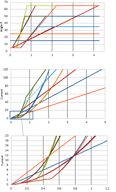
Here are some kp and current demand curves I am testing. All these are viable. I found I like a much higher maximum kp. 65 is a little too stiff. 35 and 50 are good. I designed these curves to intersect with kp 15 and 25 at .8 and .5 degrees respectively, corresponding to ~12A demand. If you are interested in giving this a try I have separated this code into a couple function right before float_thd() in branch Traction3.